W7GJ's ANTENNA FARM
| The
VHF
Crop
at W7GJ's ANTENNA FARM |
|
| 16x17
el for 2m at 27'
high (DN27UB91it) |
6M11JKV 11 el (70' long) for 6m at 70'
high (DN27UB91iu) |
4x6M9KHW 9 el for 6m 32' high (DN27UB91ju) |
The antenna was used for the first year at a height of 20', and worked surprisingly well at that height. It had a very clean pattern, an almost perfect match (couple of watts reflected at 1500 forward), and great vertical (H plane) lobes for catching E skip coming in at various angles. It proved itself to be a very efficient antenna, completing EME contacts with SM7BAE and WA4NJP. It was raised to 70' a year later, for the second summer Es season (and an easy EME contact with K6QXY). By the end of the second summer of operation, QSO's had been confirmed with 49 U.S. states, 6 Canadian provinces, and 5 DXCC countries. Although it was a fantastic performer and a joy to use, it was removed in October 1997 to make room on the top for "Big Stealth". After the demise of Big Stealth in July 1998, it was again returned to service. Before it was raised the second time, it was camo painted (earning the nickname, "Mini Stealth") and side-to-side braces were added.
Big Stealth was computer designed by VE7BQH, and had a theoretical free space gain of 13.85 dbd. Although several EME contacts were made with the previous antenna, it was felt that an improvement of almost 3 db would make it substantially easier to make EME contacts with additional stations, particularly when both stations were not favored by ground gain at the same time. A single yagi design was chosen to preserve the gain of the antenna when pointed at the horizon (the mounted antenna height here is only 3.5 wavelengths above the ground); stacked yagi arrays compromise on theoretical maximum forward gain unless all antennas in the array are electrically at the same effective elevation above ground (which only begins to happen when the array is quite high). Also, feeding, turning and elevating one big yagi is considerably easier than dealing with 2 or more yagis. In order to avoid calling attention to the antenna (which can be seen from 7 miles away on I-90), a "stealth" treatment was imparted by painting the boom a matte blue-green color (hence the nickname, "Big Stealth").
I certainly don't expect serious interest in duplicating this antenna, but enough people have asked about the construction, that I decided to provide general construction notes. For those interested in similar but much more readily available antennas of this same general size and performance (but for 50 ohm feed), I suggest directly contacting M2 Antennas.
"Big
Obvious" (B.O.) M-SQUARED MODEL #6M35WL
for
50 MHz
 |
On November 21, 1998, a 21m long 11 element highly optimized commercial yagi manufactured by M-Squared was installed on a slightly modified elevation mount (as described in the "Big Stealth" construction notes above) at a height of 21m, and became the primary 6m antenna at the station. The gain and performance of the 6M35WL is very similar to "Big Stealth", but the construction is substantially heavier and (hopefully) much more durable! The stock M2 50 ohm driven element |
| was fed with 25' of LMR600 low loss
50 ohm cable,
which carries the signals to a home-brew impedance transformer mounted
on the boom next to the elevation mount. A 10' length of RG11 75
ohm coax goes around the rotator to connect the impedance
transformer
with 185' of 3/4" 75ohm CATV hardline. This is a big, heavy
antenna,
and will require a good rotor - Yaesu G-2800SDX or larger.
The antenna can be elevated from 0 to 45 degrees for EME moon tracking and matching incoming angles of signals propagated via the ionosphere (aurora, F2, etc.). Because elevation of the antenna was anticipated, Phyllistran side-to-side braces were added front and rear (attached to the boom midway between the front and rear vertical guy lines), and tightened with turnbuckles mounted on an 8' long x 1" diameter red fiberglass pole near the center of the antenna boom. As with Big Stealth, the vertical mast that supports the 4 guy wires out to the boom (to keep it from sagging) was mounted on the front end of the elevation mount channel, so the antenna could be elevated. Unfortunately, the antenna was raised in November, in an
effort to beat
the winter weather, and it was not possible to paint the boom (as with
"Big Stealth") prior to antenna raising. "Big Obvious" can
therefore
(unfortunately) be spotted 10 miles away while driving on interstate
highway
I-90 when the sun is at the right angle. The rest of the antennas
at the farm are all hidden by conifer trees. Keeping in the tradition of trying to get the antenna work
finished before winter, the driven element was rebuilt in October 2008
and the refurbished antenna was raised in November that year.
Photos of the rebuilt driven element and finished antenna are shown here. |
 |
Four Yagi EME Array for 50
MHz
 |
Western Montana has a very high geomagnetic
latitude.
This situation is made worse by the fact that our unique position on
the
globe results in most of the ionospheric propagation paths to
other
locations running crosswise to ionospheric contours of highest
propagation
(as opposed to following along them). These two phenomenon,
coupled
with the fact that it is simply so far from here to other countries,
makes
it very difficult to make contact with other countries via the
admittedly
rare modes of ionospheric propagation up on 50 MHz.
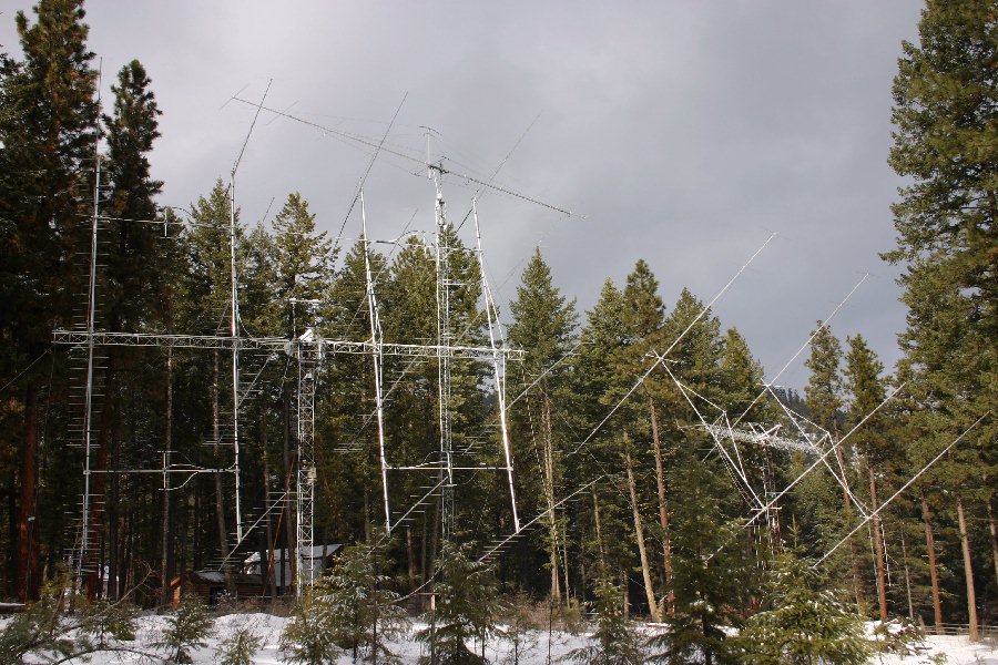
In order to help make up for this unfortunate combination of factors, it was decided to construct an antenna large enough to more reliably make contacts with larger stations in other countries by bouncing signals off the moon instead of relaying on the ionosphere. On October 27, 2001, an array of four 6M9KHW 9 element yagis was raised, in order to provide an additional 4.5 db gain over the big single yagi above, and thereby improve the chances for success in the admittedly difficult challenge of making moonbounce contacts on this frequency band. As you can see in the photo, the "GLEAP" (Geomagnetic Latitude Equalizer Antenna Project") was located 55' east of the big tower holding the single 70' yagi. Details of the design, construction and performance of this array are documented on a separate web page. |
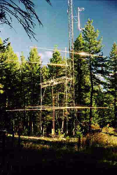
16 x 17 KLM LBX Yagis for 144 MHz
The current 2m antenna (shown below) was raised in December, 1984. It replaced previous arrays of 12x19 element Cushcraft "Boomer", 8x16 element F9FT, and 4x16 element F9FT yagis. It utilizes 75 ohm 3/4" CATV hardline for phasing lines, connecting directly to the custom 75 ohm feeds of each antenna. The four four-way power dividers are custom made for splitting 75 ohms all all ports; the center four-way power divider splits the main 50 ohm feedline (1-5/8" gas Heliax) into four 75 ohm ports. CATV "entry fittings" were used to connect the CATV hardline to the power dividers. The receiving preamplifier an Transmit/Receive relays are mounted directly on the center power divider. A unique (at the time) innovation for these yagis was to incorporate the vertical truss supports at the center of each yagi directly into the boom-to-mast clamp for the yagi. This means that each yagi can be properly trussed before putting it up into the array.
The main boom of the array is 48' of Heights
14"
aluminum tower (which has twisted slightly), trussed in the middle
(front
and top) with Phyllistran cable. The four uprights are 3" aluminum
irrigation
tubing, with rigid bracing in the middle and wire trussing to the tops
and bottoms. Horizontal bracing is accomplished by trusses running to
the
horizontal tower boom, and through the use of 3/4" aluminum tubing
running
horizontally through the array (which also supports the phasing lines
and
power dividers).
![]()