6M11JKV Driven Element at W7GJ
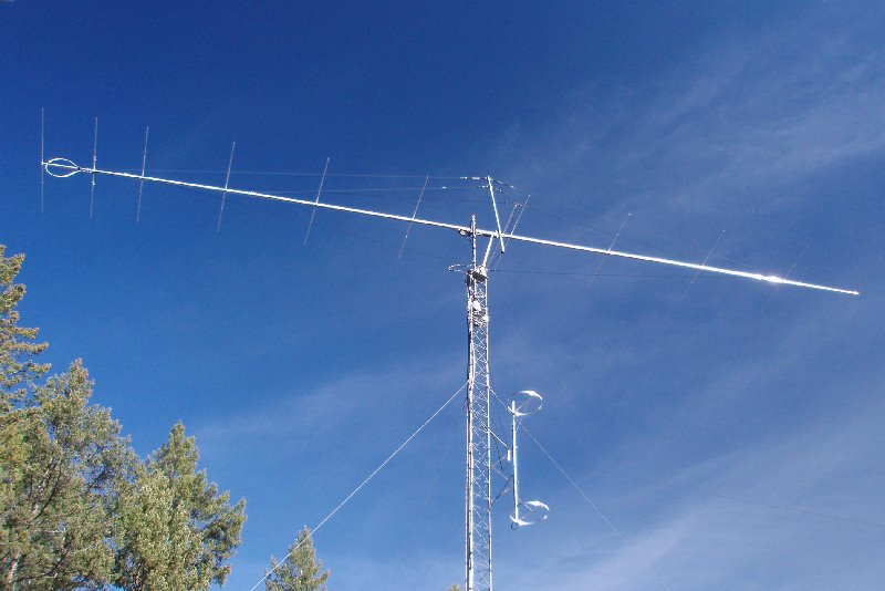
| The
rebuilt 6M11JKV Driven Element at W7GJ |
 |
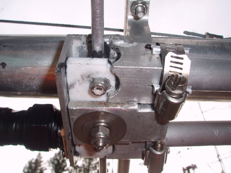 |
In October 2008,
driven element was rebuilt to more reliably provide QRO service.
The standard M2 DE connector block and RG6-U balun was removed, and the
same T bar spacing and mounting bolt hole were preserved., although a
longer stainless steel mounting bolt was used to hold the sanwich
of components together. A new mounting assembly was constructed from several different sizes of angle aluminum, some HDPE spacer blocks, a 1/4" teflon mounting block and a 7/16 DIN connector. All electrical connections were made with a pair of #8 stainless steel screws, mounted 2-1/4" apart in the teflon block. New T bars were fabricated from a 4' long piece of 1/4" aluminum rod purchased at the hardware store. The last half inch of one end of each aluminum T bar was flattened to 1/8" and drilled for a #8 screw. The same shorting bar positions and extensions past the shorting bars were maintained with the new T bars and matching block. |
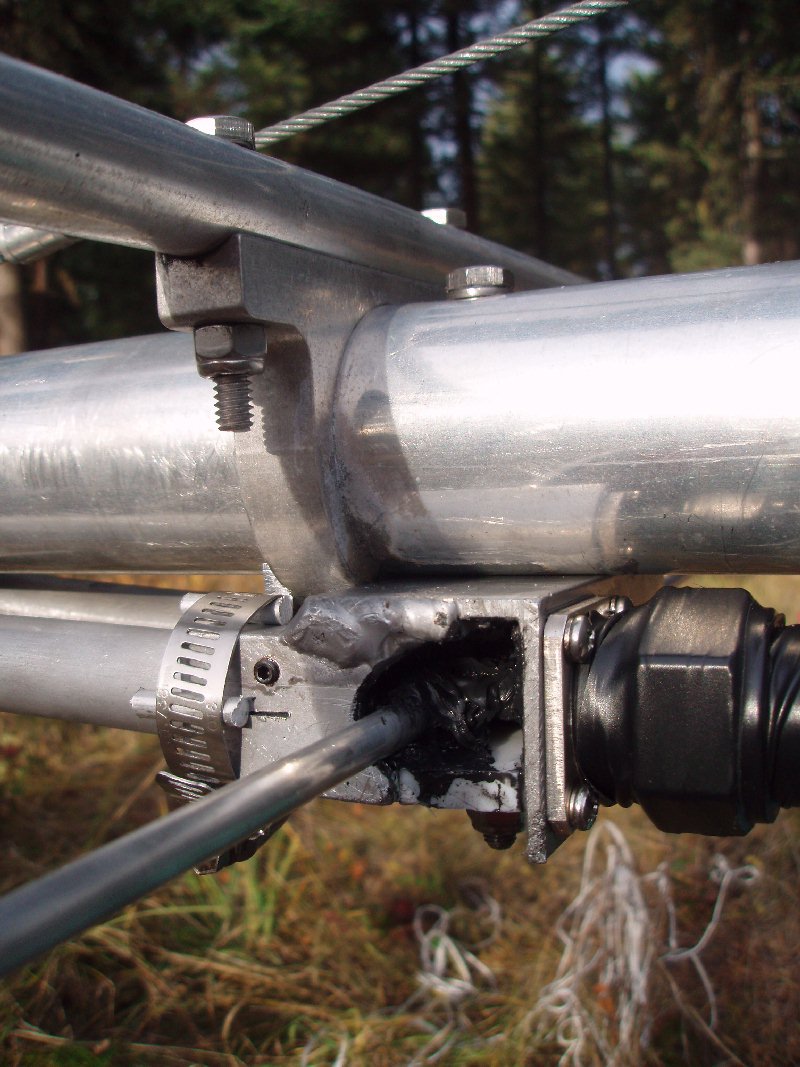 |
The 1/2 wavelength balun was
made from 75 ohm 3/4" CATV CATV hardline. Several different
alternatives were investigated, but the CATV hardline was finally
selected because it is lightweight, very robust in power handling, and
very stable in an outdoor environment. Ring screw eyes were
soldered to the ends of the center conductor. The connection to
the shield was made by inserting the ends of the balun into short
pieces of 1"x1" square aluminum tubing with 1/8" wall. As you can
see in the photo, a set screw holds the cable tightly in the aluminum
tubing. Further cinching down around the hardline was achieved by
slotting the ends of the tubing and compressing the tubing around the
hardline with stainless steel hose clamps. The electrical connections were all treated with aluminum anti-seize compound during assembly and then wiped and covered with Dow 739 non-contaminating silicone caulking. |
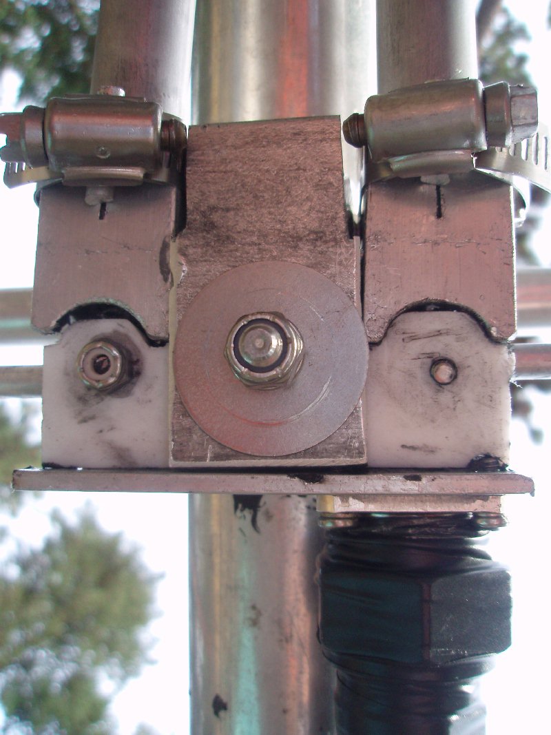 |
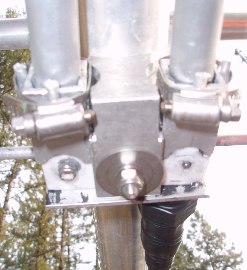
The two views from the bottom better show the bottom plate, which holds together all the components of the mounting assembly. The bottom plate actually wraps around the back of the bottom of the mounting bracket for the driven element itself, and is contoured to fit up tightly against the boom. The mounting assembly is very securely attached to the boom with only the single mounting bolt coming down through the center of the boom and all the layers of the assembly. |
 |
|
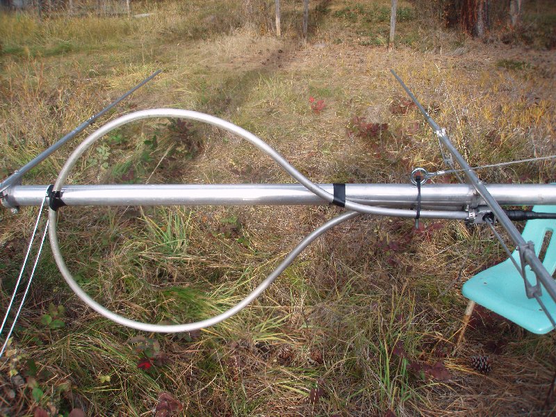 |
The balun cable needed to be
bent in a 1' radius to prevent kinking. A 2' diameter automobile
tire was used as a form for bending the balun. The balun was oriented
vertically so it would not interact with with the horizontally
polarized antenna elements. Connection to the driven element assembly was made with a 40' long piece of LMR600 Ultra Flex, having 7/16 DIN connectors at both ends. At the top of the tower this transfers to a 175' run of 1-5/8" Heliax that runs into the ham shack. |
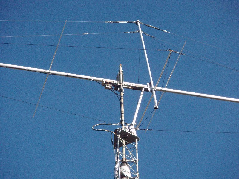 |
While the antenna was down on
the ground, the horizontal fiberglass spreader for the Phyllstran side
guys was painted white with 3 coats of special marine grade epoxy paint
for treating fiberglass boats. The newly paited spreader can be
seen in this photo of the elevation mount just after the refurbished
antenna was re-installed at 70'. |