W7GJ "BQH7A"50
MHZ YAGI CONSTRUCTION DETAILS
The "BQH7A"
Antenna - A 7 Element Yagi for 50.2 MHz
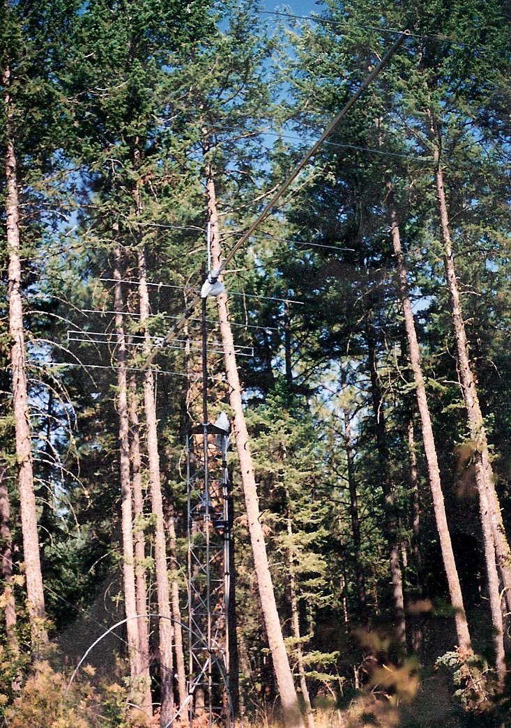
In the photo shown
above, the 11 dBD antenna is mounted
at 20' above ground, in 15' of Rohn 45 tower (which eventually was
expanded to 65'). the antenna was fed with 3/4" CATV hardline,
and as
shown was successful in working SM7BAE and WA4NJP on 6m EME using CW. The main boom is 2" diameter aluminum irrigation
tubing (.050" wall), vertically braced front and rear with 1/8"
aircraft
guy cable. The guy locations are were from the front of the mount to
just
ahead of the DE and just ahead of D4. Phyllistran 1200 nonconducting
guy
cable is used for side-to-side bracing from the center to the front and
rear vertical guy locations of the antenna. The antenna was used
successfully for a year without the side-side bracing, but this was
added
as a precaution when it was put up the second time (to replace "Big
Stealth",
when it came apart due to wind damage). The Phyllistran cable was
held to the side from the center of the array with an 1"x8' fiberglass
pole (4' on either side of the boom).
The antenna is mounted at the center of
gravity,
which is just in front of the second director. PVC plugs (made
for
PVC plumbing pipe) are inserted in both the front and rear ends to
close
off the irrigation tubing. Each plug adds 1" to the length of the
antenna.
1.5" PVC schedule 80 high pressure pipe was also
used to provide additional strength to the boom where elements holes
were
drilled. 3" long pieces were inserted and centered at Reflector and
D4-D5
locations, a 6" long piece was use at the D1 location, and an 18" long
piece was used under the DE mounting clamps. A 72" long piece was
inserted in between elements D2 and D3 (and extending equally past the
holes on either side), not just to provide extra strength where the
elements
are mounted, but to prevent collapse of the tubing where the 5 central
U bolts hold it to the mounting channel.
 The
elements are 3/8" diameter 6061T6 aluminum tubing (.035" wall), mounted
through the boom (insulated with nylon bushings manufactured for bed
casters).
The driven element is a folded dipole constructed of 1/2" diameter
6061T6
aluminum tubing (.058" wall), and was designed to provide a feed
impedance
of 75 ohms. The top and bottom of the folded dipole sections are spaced
4" apart (center-to-center), and shorted with 1/2" wide aluminum straps
on the ends. The driven element sections are clamped to 1/2" thick HDPE
plastic plates, which in turn are bolted above and below the boom using
muffler clamp parts. To strengthen the driven element pieces where they
were clamped to the plastic mounting plates, 12" long x 3/8" diameter
reinforcing
inserts were inserted into the middle of the top and bottom of the
folded
dipole elements (aluminum tubing in the continuous top section, and
nylon
in the split bottom section).
The
elements are 3/8" diameter 6061T6 aluminum tubing (.035" wall), mounted
through the boom (insulated with nylon bushings manufactured for bed
casters).
The driven element is a folded dipole constructed of 1/2" diameter
6061T6
aluminum tubing (.058" wall), and was designed to provide a feed
impedance
of 75 ohms. The top and bottom of the folded dipole sections are spaced
4" apart (center-to-center), and shorted with 1/2" wide aluminum straps
on the ends. The driven element sections are clamped to 1/2" thick HDPE
plastic plates, which in turn are bolted above and below the boom using
muffler clamp parts. To strengthen the driven element pieces where they
were clamped to the plastic mounting plates, 12" long x 3/8" diameter
reinforcing
inserts were inserted into the middle of the top and bottom of the
folded
dipole elements (aluminum tubing in the continuous top section, and
nylon
in the split bottom section).
At the feed, 75 ohm hardline is directly
attached
(using stainless steel hardware, and completely potted in non-acetic
acid
silicone caulking) and immediately followed with a quarter wavelength
decoupling
sleeve insulated from the boom (built using 2" irrigation tubing
and PVC plumbing fittings for spacers). The antenna is fed with 185' of
75 ohm 3/4" CATV hardline (not including the section of hardline
mounted
on the boom, between the driven element and the flexible 10' piece of
RG-11
around the mast to the top of the tower).
 The
boom-to-mast connection mount the first time was a simple aluminum
plate
U-bolts and muffler clamp saddles. The second time it was put up,
it was mounted on the "Big Stealth" elevation mount assembly. In
this mount, the antenna boom was mounted on a 3.5' long piece of 4"
wide
structural aluminum channel. This same aluminum channel was used to
construct
a "box" into which the piece with the antenna on it tightly fit inside.
On the rear and bottom of this box, the channel holding the antenna was
supported by a pivot assembly (which takes all the weight when the
antenna
is elevated). The pivoting shaft permits elevation of the antenna up to
50 degrees (and is shown in the photo at an angle of 45 degrees). The
pivot
assembly is a shaft of 1.5" IPS steel pipe inside a sleeve of 2" IPS
schedule
80 steel pipe. This leaves a small space between the two pipes, which
was
shimmed with a single layer of thin teflon sheet, to serve as a bearing
between them. A smaller piece of aluminum channel was clamped onto the
pivoting sleeve. The 4" wide piece attached to the antenna boom fits
over
this shorter and upside-down pivoting section of channel, and the two
mating
channel sections (one fastened to the antenna boom and the other to the
mount) are secured together with two hardened 7/16" through bolts.
The
boom-to-mast connection mount the first time was a simple aluminum
plate
U-bolts and muffler clamp saddles. The second time it was put up,
it was mounted on the "Big Stealth" elevation mount assembly. In
this mount, the antenna boom was mounted on a 3.5' long piece of 4"
wide
structural aluminum channel. This same aluminum channel was used to
construct
a "box" into which the piece with the antenna on it tightly fit inside.
On the rear and bottom of this box, the channel holding the antenna was
supported by a pivot assembly (which takes all the weight when the
antenna
is elevated). The pivoting shaft permits elevation of the antenna up to
50 degrees (and is shown in the photo at an angle of 45 degrees). The
pivot
assembly is a shaft of 1.5" IPS steel pipe inside a sleeve of 2" IPS
schedule
80 steel pipe. This leaves a small space between the two pipes, which
was
shimmed with a single layer of thin teflon sheet, to serve as a bearing
between them. A smaller piece of aluminum channel was clamped onto the
pivoting sleeve. The 4" wide piece attached to the antenna boom fits
over
this shorter and upside-down pivoting section of channel, and the two
mating
channel sections (one fastened to the antenna boom and the other to the
mount) are secured together with two hardened 7/16" through bolts.
Elevation indication is achieved through a
weighted
shaft on a potentiometer installed in the round film can mounted under
the channel holding the boom. The potentiometer is part of a Wheatstone
Bridge arrangement, which indicates elevation in the shack (thanks to
G4ZHI
for the circuit
details)
. Elevation was incorporated into the antenna for two reasons. The
usable
window for EME contacts with various stations overseas is greatly
expanded
by providing elevation for at least one station. Second, the local
horizon,
especially to the north, is impaired by a 3000' higher mountain ridge
peaking
5 miles from the antenna; the effective horizon is 10-15 degrees toward
the north, and does not drop down to zero until around 240 and 120
degrees
azimuth. A surplus Luxor TVRO actuator easily provides the necessary
mechanical
force to raise the front of the boom to elevate the balanced antenna.
BQH7A Antenna Element Layout
|
ELEMENT
|
OVERALL
LENGTH "
|
" DISTANCE
FROM REFLECTOR
|
| Reflector |
116.235 |
0 |
| Driven Element |
109.4 |
46.8553 |
| Director 1 |
107.325 |
85.5994 |
| Director 2 |
106.2 |
125.7021 |
|
Center of Balance and Location of
Mount
|
| Director 3 |
105.7 |
191.2506 |
| Director 4 |
105.321 |
278.5920 |
| Director 5 |
103.971 |
354 |
