W7GJ "BIG
STEALTH" 50 MHZ YAGI CONSTRUCTION DETAILS
 The
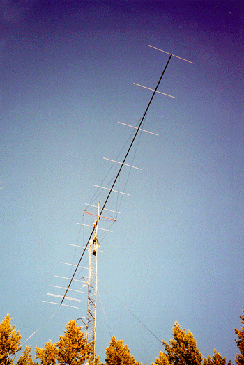
W7GJ "Big Stealth"
(B.S.) Antenna - A 13 Element Yagi for 50.1 MHz
The main boom is 2" diameter aluminum irrigation
tubing (.050" wall), vertically braced in two places both front and rear
with 1/8" aircraft guy cable. Phyllistran 1200 non conducting guy cable
is used for side-to-side bracing two places in each the front and rear
halves of the antenna. Additional 8' fiberglass braces later were
added out each side from the center of the antenna to provide connections
for additional Phyllistran side-to-side bracing lines that ran out to the
front-most brace connection position (just to the rear of the second element
from the front of the yagi). It was found that this greater angle
was required to keep the front of the antenna from flexing excessively
during high winds.
(Where the "Big Stealth" antenna eventually failed,
however, was in the rear half of the yagi, right where the PVC center stiffener
ended. Apparently, extremely high winds caused uplift of the rear
of the antenna, creating metal fatigue at that point. The aluminum
irrigation tubing used for the Big Stealth boom is not designed to withstand
the repeated flexing as well as the 6061T6 aluminum alloy used in commercial
antennas. Big Stealth was replaced in November 1998 by a commercial
equivalent - the M Squared model "6M35WL", which is constructed using much
sturdier and heavier materials. The 6M35WL has an overall length
of 69.5').
A 40' long piece of irrigation tubing was used
from the center of the yagi to the front of the array, and a 30' long piece
of irrigation tubing was cut to 28'-4" to form the rear half. A spreadsheet
was created to incrementally analyze the projected antenna weight at every
inch along its entire length ( in order to select the lengths and locations
of PVC plugs, hardware locations, etc.), so the joint would be supported
near the center of gravity. The antenna is mounted at the center of gravity,
which is only 2" to the rear of the joint between the two pieces of aluminum
tubing forming the boom. PVC plugs (made for PVC plumbing pipe) are inserted
in both the front and rear ends to close off the irrigation tubing. Each
plug adds 1" to the length of the antenna, making the overall length 68.5'.
1.5" PVC schedule 80 high pressure pipe was also
used to provide additional strength to the boom where elements holes were
drilled. 3" long pieces were inserted and centered at D1-D4 locations,
and 6" long pieces were centered at D7-D10 locations. An 8" long piece
was positioned under the U bolts holding the driven element mounting plates
in place. A 73" long piece was inserted in between elements D5 and D6 (and
extending 3" past the holes on either side), not just to provide extra
strength where the elements are mounted, but to prevent collapse of the
tubing where the 5 central U bolts hold it to the mounting channel.
 The
elements are 3/8" diameter 6061T6 aluminum tubing (.035" wall), mounted
through the boom (insulated with nylon bushings manufactured for bed casters).
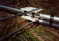
The driven element is a folded dipole constructed of 1/2" diameter 6061T6
aluminum tubing (.058" wall), and was designed to provide a feed impedance
of 75 ohms. The top and bottom of the folded dipole sections are spaced
4" apart (center-to-center), and shorted with 1/2" wide aluminum straps
on the ends. The driven element sections are clamped to 1/2" thick HDPE
plastic plates, which in turn are bolted above and below the boom using
muffler clamp parts. To strengthen the driven element pieces where they
were clamped to the plastic mounting plates, 12" long x 3/8" diameter reinforcing
inserts were inserted into the middle of the top and bottom of the folded
dipole elements (aluminum tubing in the continuous top section, and nylon
in the split bottom section).
The
elements are 3/8" diameter 6061T6 aluminum tubing (.035" wall), mounted
through the boom (insulated with nylon bushings manufactured for bed casters).
The driven element is a folded dipole constructed of 1/2" diameter 6061T6
aluminum tubing (.058" wall), and was designed to provide a feed impedance
of 75 ohms. The top and bottom of the folded dipole sections are spaced
4" apart (center-to-center), and shorted with 1/2" wide aluminum straps
on the ends. The driven element sections are clamped to 1/2" thick HDPE
plastic plates, which in turn are bolted above and below the boom using
muffler clamp parts. To strengthen the driven element pieces where they
were clamped to the plastic mounting plates, 12" long x 3/8" diameter reinforcing
inserts were inserted into the middle of the top and bottom of the folded
dipole elements (aluminum tubing in the continuous top section, and nylon
in the split bottom section).
At the feed, 75 ohm hardline is directly attached
(using stainless steel hardware, and completely potted in non-acetic acid
silicone caulking) and immediately followed with a quarter wavelength decoupling
sleeve (built using 2" irrigation tubing and PVC plumbing fittings for
spacers), followed by 8 ferrite toroids (heat shrink wrapped) around the
hardline. The antenna is fed with 185' of 75 ohm 3/4" CATV hardline (not
including the 25' section of hardline mounted on the boom, between the
driven element and the flexible 10' piece of RG-11 around the mast to the
top of the tower).
 The
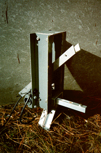
antenna boom was mounted on a 3.5' long piece of 4" wide structural aluminum
channel. This same aluminum channel was used to construct a "box" into
which the piece with the antenna on it tightly fit inside. On the rear
and bottom of this box, the channel holding the antenna was supported by
a pivot assembly (which takes all the weight when the antenna is elevated).
The pivoting shaft permits elevation of the antenna up to 50 degrees (and
is shown in the photo at an angle of 45 degrees). The pivot assembly is
a shaft of 1.5" IPS steel pipe inside a sleeve of 2" IPS schedule 80 steel
pipe. This leaves a small space between the two pipes, which was shimmed
with a single layer of thin teflon sheet, to serve as a bearing between
them. A smaller piece of aluminum channel was clamped onto the pivoting
sleeve. The 4" wide piece attached to the antenna boom fits over this shorter
and upside-down pivoting section of channel, and the two mating channel
sections (one fastened to the antenna boom and the other to the mount)
are secured together with two hardened 7/16" through bolts.
The
antenna boom was mounted on a 3.5' long piece of 4" wide structural aluminum
channel. This same aluminum channel was used to construct a "box" into
which the piece with the antenna on it tightly fit inside. On the rear
and bottom of this box, the channel holding the antenna was supported by
a pivot assembly (which takes all the weight when the antenna is elevated).
The pivoting shaft permits elevation of the antenna up to 50 degrees (and
is shown in the photo at an angle of 45 degrees). The pivot assembly is
a shaft of 1.5" IPS steel pipe inside a sleeve of 2" IPS schedule 80 steel
pipe. This leaves a small space between the two pipes, which was shimmed
with a single layer of thin teflon sheet, to serve as a bearing between
them. A smaller piece of aluminum channel was clamped onto the pivoting
sleeve. The 4" wide piece attached to the antenna boom fits over this shorter
and upside-down pivoting section of channel, and the two mating channel
sections (one fastened to the antenna boom and the other to the mount)
are secured together with two hardened 7/16" through bolts.
Elevation indication is achieved through a weighted
shaft on a potentiometer installed in the round film can mounted under
the channel holding the boom. The potentiometer is part of a Wheatstone
Bridge arrangement, which indicates elevation in the shack. Elevation was
incorporated into the antenna for two reasons. The usable window for EME
contacts with various stations overseas is greatly expanded by providing
elevation at at least one station. Second, the local horizon, especially
to the north, is impaired by a 3000' higher mountain ridge peaking 5 miles
from the antenna; the effective horizon is 10-15 degrees toward the north,
and does not drop down to zero until around 240 and 120 degrees azimuth.
A surplus Luxor TVRO actuator easily provides the necessary mechanical
force to raise the front of the boom to elevate the antenna.
The stacked 6m halos, more important now that
a very directional antenna is being employed most of the time, were lowered
down the tower, to be 18' below the boom just out of the pattern so there
is no interaction between the antennas.
Big Stealth Element Layout
|
ELEMENT
|
OVERALL
LENGTH "
|
" DISTANCE
FROM REFLECTOR
|
| Reflector |
116.2699 |
0 |
| Driven Element |
106.5 |
34.2202 |
| Director 1 |
108.5531 |
73.543 |
| Director 2 |
105.0389 |
117.9233 |
| Director 3 |
105.5161 |
173.6502 |
| Director 4 |
104.6083 |
248.058 |
| Director 5 |
103.4279 |
328.3095 |
|
Center of Balance and Location of Mount
|
| Director 6 |
99.5753 |
396.7612 |
| Director 7 |
101.3621 |
460.3414 |
| Director 8 |
102.1781 |
543.2365 |
| Director 9 |
102.1657 |
643.5047 |
| Director 10 |
102.8873 |
738.8214 |
| Director 11 |
103.8887 |
820 |

 The
elements are 3/8" diameter 6061T6 aluminum tubing (.035" wall), mounted
through the boom (insulated with nylon bushings manufactured for bed casters).
The driven element is a folded dipole constructed of 1/2" diameter 6061T6
aluminum tubing (.058" wall), and was designed to provide a feed impedance
of 75 ohms. The top and bottom of the folded dipole sections are spaced
4" apart (center-to-center), and shorted with 1/2" wide aluminum straps
on the ends. The driven element sections are clamped to 1/2" thick HDPE
plastic plates, which in turn are bolted above and below the boom using
muffler clamp parts. To strengthen the driven element pieces where they
were clamped to the plastic mounting plates, 12" long x 3/8" diameter reinforcing
inserts were inserted into the middle of the top and bottom of the folded
dipole elements (aluminum tubing in the continuous top section, and nylon
in the split bottom section).
The
elements are 3/8" diameter 6061T6 aluminum tubing (.035" wall), mounted
through the boom (insulated with nylon bushings manufactured for bed casters).
The driven element is a folded dipole constructed of 1/2" diameter 6061T6
aluminum tubing (.058" wall), and was designed to provide a feed impedance
of 75 ohms. The top and bottom of the folded dipole sections are spaced
4" apart (center-to-center), and shorted with 1/2" wide aluminum straps
on the ends. The driven element sections are clamped to 1/2" thick HDPE
plastic plates, which in turn are bolted above and below the boom using
muffler clamp parts. To strengthen the driven element pieces where they
were clamped to the plastic mounting plates, 12" long x 3/8" diameter reinforcing
inserts were inserted into the middle of the top and bottom of the folded
dipole elements (aluminum tubing in the continuous top section, and nylon
in the split bottom section).
 The
W7GJ "Big Stealth"
(B.S.) Antenna - A 13 Element Yagi for 50.1 MHz
 The
antenna boom was mounted on a 3.5' long piece of 4" wide structural aluminum
channel. This same aluminum channel was used to construct a "box" into
which the piece with the antenna on it tightly fit inside. On the rear
and bottom of this box, the channel holding the antenna was supported by
a pivot assembly (which takes all the weight when the antenna is elevated).
The pivoting shaft permits elevation of the antenna up to 50 degrees (and
is shown in the photo at an angle of 45 degrees). The pivot assembly is
a shaft of 1.5" IPS steel pipe inside a sleeve of 2" IPS schedule 80 steel
pipe. This leaves a small space between the two pipes, which was shimmed
with a single layer of thin teflon sheet, to serve as a bearing between
them. A smaller piece of aluminum channel was clamped onto the pivoting
sleeve. The 4" wide piece attached to the antenna boom fits over this shorter
and upside-down pivoting section of channel, and the two mating channel
sections (one fastened to the antenna boom and the other to the mount)
are secured together with two hardened 7/16" through bolts.
The
antenna boom was mounted on a 3.5' long piece of 4" wide structural aluminum
channel. This same aluminum channel was used to construct a "box" into
which the piece with the antenna on it tightly fit inside. On the rear
and bottom of this box, the channel holding the antenna was supported by
a pivot assembly (which takes all the weight when the antenna is elevated).
The pivoting shaft permits elevation of the antenna up to 50 degrees (and
is shown in the photo at an angle of 45 degrees). The pivot assembly is
a shaft of 1.5" IPS steel pipe inside a sleeve of 2" IPS schedule 80 steel
pipe. This leaves a small space between the two pipes, which was shimmed
with a single layer of thin teflon sheet, to serve as a bearing between
them. A smaller piece of aluminum channel was clamped onto the pivoting
sleeve. The 4" wide piece attached to the antenna boom fits over this shorter
and upside-down pivoting section of channel, and the two mating channel
sections (one fastened to the antenna boom and the other to the mount)
are secured together with two hardened 7/16" through bolts.