BACKGROUND
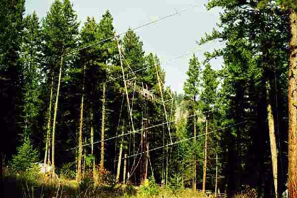
Yes, I undertook the HUGE process of building an array of four of the 50' long M-Squared 6M9KHW yagis - I highly recommend this array as a "realistically manageable" size, yet with enough gain to really get the job done effectively. At the time of its raising (October 27, 2001), it was the third largest fully steerable ham radio antenna array for this frequency band in the world. "Why is it so important to have a fully steerable antenna?", you might ask.
There are very few 6m DX stations with EME tracking capability,
so it is ESSENTIAL (at this latitude anyway), to have elevation
capability up to 65 degrees. With my single yagi, I can only
elevate to 45 degrees, which is really unfortunate because I was
missing EU moonset under the best times of month (which in 2001
were coinciding with most northerly declination, putting the
moonVERY HIGH here!). The new GLEAP array is capable of
elevation to around 70 degrees before the cross booms hit the
motor mounted on the rear of the mast.
It is very desirable to have at least 1500W on 6m EME if you want to have any success. Conditions on 6m can be VERY erratic - it is a terrible band for EME....however, it is the ONLY way to work any 6m DX from up here in the "geomagnetic far north". I think if you put up an array such as four of the 6M9KHW yagis, you will have a killer system for working other kinds of propagation, too (if you happen to live in a place that HAS any other kind of propagation). And, it should be possible to more easily work DX stations on their moonset with a 6m amplifier and a single good yagi.
Most of the folks who have tried 6m EME and given up due to lack of success and/or activity have had very little antenna gain, so have been severely limited by the number of larger stations they could work. Note that even a four bay array of 5 or 6 element yagis only has the same amount of gain as my single 6M35WL/6M11JKV yagi, which I consider to be the minimum antenna size for 6m EME. With my single yagi, I DO hear my own echoes when I am pointed skyward (no ground gain) and the conditions are optimum (quiet background sky, moon near perigee, no auroral disturbances, etc.) but performance is quite erratic. Just as on 2m EME, though, there is a "magic minimum point" in antenna gain where you can begin to have some reasonable success....and increasing the gain above that point dramatically increases the number of stations you will be able to contact. The 4.5 dB additional gain from this four yagi array greatly improves the reliability for EME QSO's with other smaller stations.
MINIMUM ARRAY SIZE
Having said all that about my array, I have to add now that very
successful 6m EME results can now be obtained by using JT65A mode
and a smaller array. I truly believe that a very practical
sized array for success using JT65A is an array of four 6M5X
yagis. This sized array is very simple to build and elevate,
and has approximately the same gain as my single yagi, with which
I hear my own echoes while pointing upward. As long as it
has 14 or 15 dBd gain, such a steerable array should have no
trouble making contacts with larger 6m stations on CW, or with
many stations on their horizon using JT65A. I suggest
constructing such an array using a "Double H frame" of aluminum
tubing. It could be very conveniently mounted on a 25' high
tower.When this array was built, only JT44 mode (the early
precursor to JT65A) was available. JT65A has since become
the worldwide standard for 6m EME contacts.
MY ARRAY DESIGN
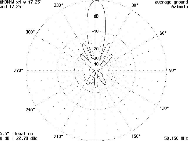
The array was designed to be able to provide a stacking distance of 31'' wide x 29.5' high, with the center of the array at 32' above ground level. Here is the expected performance of the array:
Azimuthal pattern (courtesy of K0GU):
Elevation pattern (courtesy of K0GU):
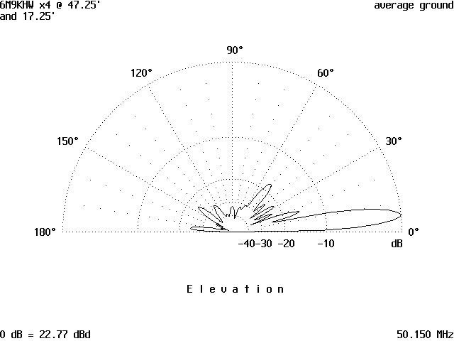
While pointed at the horizon, the new array appears to have more
gain than the maximum ground gain lobe of the single
6M35WL/6M11JKV at 70', over the entire range of 2.5 to 9.5 degrees
elevation. Therefore, I expect it to be a very good
performer when the moon is on the horizon, as well as for use on
ground wave and during ionospheric openings.
| SPACE PLANNING AND PREPARATION | ||
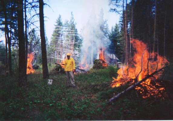 |
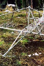
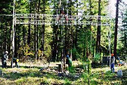
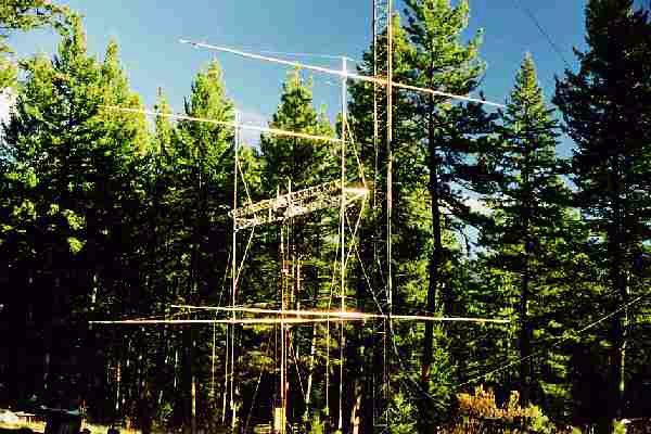
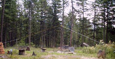
Over 2 dozen trees were cut down and
stacked in the spring of 2001 to make room for the new
array. Before any excavation could be done, all
the slash (the limbs) needed to be burned. Here we
are rushing to burn the slash in the spring before it
becomes too dry, and they no longer permit such burning.
(You can see the 2m EME array is in the background).
Clearance for the array was calculated using my old
DOS program "SPACE" . To the right is a
printout from that program, showing what the
clearance looks like for this array. An Excel
Spreadsheet version of this program is now available
for free on my website HERE. Although there is some ground interaction with the array because it is so low, I find that it works very successfully when I aim directly at the moon when it is above 10 degrees elevation. That is also the elevation where most of the local noise drops off. As you can see from the table below, the minimum ground clearance when the array is elevated is still high enough to clear the messenger cable with the feedline, as well as deep snow. |
CLEARANCE CALCULATIONS FOR ARRAY OF FOUR 6M9KHW 6M YAGIS AT W7GJ HORIZONTAL SPACING
BETWEEN
TOWER
HEIGHT=
32 ELEVATION GROUND CLEARANCE TURNING CLEARANCE TURNING IN DEGREES CLEARANCE HEIGHT RADIUS HEIGHT RADIUS ========== ========= ========= ======= ========= ======= 0 17.25 17.25 33.51 46.75 30.35 5 15.35 19.66 34.47 44.73 31.25 10 13.57 22.16 35.27 42.62 32.03 15 11.93 24.74 35.89 40.42 32.68 20 10.44 27.37 36.32 38.17 33.18 25 9.12 30.04 36.56 35.86 33.53 30 7.98 32.73 36.61 33.52 33.71 35 7.01 35.40 36.46 31.18 33.74 40 6.24 38.06 36.11 28.84 33.60 45 5.66 40.66 35.57 26.52 33.30 50 5.28 43.20 34.86 24.25 32.85 55 5.11 45.66 33.97 22.03 32.24 60 5.14 48.01 32.93 19.89 31.50 65 5.37 50.24 31.75 17.84 30.63 70 5.81 52.33 30.45 15.90 29.66 75 6.45 54.26 29.07 14.08 28.60 80 7.28 56.03 27.63 12.40 27.48 85 8.30 57.61 26.17 10.87 26.32 90 9.50 59.00 24.73 9.50 25.15 |
| THE TOWER | |
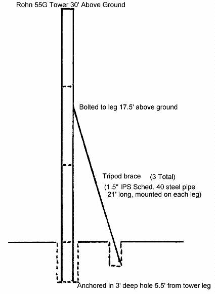 |
The center of the antenna is 32' high, which will allow
me to reach the DE on each yagi with a tall stepladder if
I need to for some reason. This low antenna height
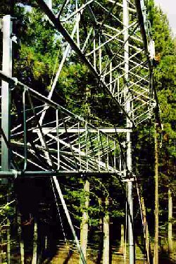
means I will not need guys. I am using 35' of Rohn
55G tower (with the bottom 5' anchored in concrete), with
"tripod guys" of 1-7/8" OD diameter steel pipe (three
pieces of 1.5" IPS Schedule 40 pipe x 21' long) solidly
supporting the tower at the 17-1/2' height, and anchored
in concrete 5.5' from each tower leg ( in 18" diameter
holes, 3' deep). Back fill from all the holes was
piled up over the locations of the tripod guy pipe
anchors, in order to increase the frost protection for the
concrete bases.
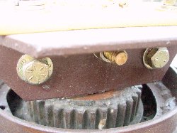
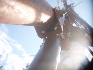
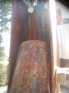
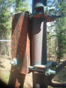
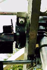
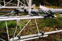
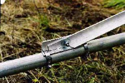
The bottom of each brace has rebar through it to attach it to the concrete, and the top end is fastened with a single large bolt, through the brace placed into the center of an 8" length of steel channel (which is bolted to each tower leg). This is the same support system I have used for decades on my 16 yagi 2m EME array. Below are some photos showing how the braces are attached to the tower:
|
 |
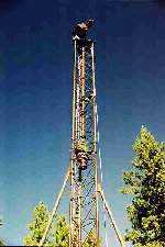
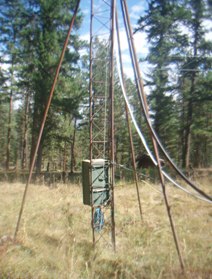
The lower 25' of tower
was assembled and single-handedly positioned in the hole
with the assistance of a "skyhook", which was a pulley
hanging on a 1" diameter nylon rope between two
trees. A come-along winch was used to pull the line
going up through the pulley and down to the tower.
The tower was held plumb during pouring of the concrete
through the use of come-along winches attached to
polypropylene ropes attached to the top of the second
section. The top section can be seen sitting on a
cable spool in the left of the photo below.
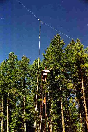
The top section of tower was also added by me alone,
using the "skyhook" lines. The photo to the left
shows me atop the complete tower, along with the
hoisting ropes hanging overhead. |
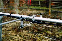
| MAST AND MOUNT | ||
|
The mast is 1.5" IPS schedule 40 steel,
with 1.5" steel tubing (.120" wall) welded inside
it. Atop the mast is a 31" long piece of 1-15/16"
steel shaft welded to atop a 26" long piece of 6" wide
steel channel, braced by pieces of 3" wide steel
channel, which extend down to the mast at a 45 degree
angle. 2"x2" steel angle is welded on both sides of
the shaft ends and top. An 8"x8"x1/8" steel mounting
plate is welded at the intersection of the braces and
masts. This mounting plate, along with a large piece
of 6" wide aluminum channel, provide the attachment points
for the reversible DC gearmotor (which requires 200 VDC),
right angle reduction gearbox, and idler sprockets
for the elevation drive chain.
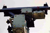
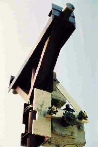
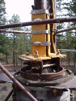
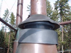
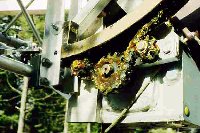
These photos show the mount on the top of the tower,
with the weather cover removed over the gearmotor,
gearbox, drive/idler sprockets. The photo at the
left shows the elevation chain and antenna installed. A
diagram of the construction of the mount is shown in the
document describing my Double H Frame construction HERE.
As explained further down this page, I used aluminum
towers for the two cross booms in the Double H Frame
construction for this array. In previous smaller 4
yagi arrays, I just used tubing for the cross booms. |
 |
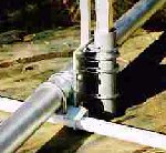
| THE ROTATOR | ||
   |
The rotator is a "medium sized" prop pitch
motor. This size motor just barely fits inside the
tower, but cannot be installed through the assembled
tower, and had to be mounted before the top section of
tower was lowered over it and bolted in place. In
usual fashion, the prop pitch motor itself is bolted to
the underside of the motor mounting plate. A
circular 1" high strap was welded to the rotor mounting
plate to act as a barrier to prevent water from running
down into the top of the motor. You must protect the
prop pitch from weather coming down inside the center of
the motor. A mast bearing was installed on the plate on
top of the tower, as well as another bearing about halfway
down the mast inside the tower. This prevents any
side pressure on the rotor from the mast. The mast extends
full length down inside the tower, to permit the rotator
to be mounted close to where the tower braces are
attached. This also helps prevent tower twisting
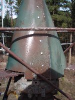
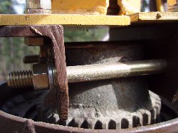
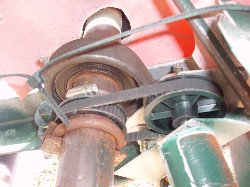
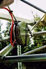
when torque is transferred to the rotator. The unit used had a pipe fitting welded inside the drive sprocket, so a mast coupler was fabricated to attach to this fitting. Inside the center of the bevel gear, a pipe adapter (of almost the same diameter as the inside of the bevel gear) had been welded, as you can see in the top photo to the right. What I decided would be easiest to do, would be to attach my mount to that pipe adapter. As you can see in photos, I sawed with a hack saw, and filed to create two flat faces on the pipe flange so that I could place some 2" angle iron (painted brown) against those flats on each side. I then secured these two pieces of angle iron on opposite flattened sides of the the pipe flange with (3) 3/8" diameter hardened bolts. The two outer bolts go around the pipe flange. The center bolt sits in a slot that I filed into the two edges of the pipe flange; this center bolt resting in the slots, and the two opposite angle iron pieces tightened against the flattened faces of the pipe adapter, makes the flange assembly very well seated so it will NOT slip. Then, onto the top of this platform formed by the two brown angle iron pieces, I bolted the yellow mast clamp assembly, which is shown in photo to the left. It was mounted onto the brown angle flanges so that the mast would be centered directly over the center of the prop pitch axis. The yellow mast clamp was made in two halves. Each half has a piece of angle iron welded to a piece of iron plate. Hose clamps were then used to tighten the clamp halves around the mast, and the clmap was then bolted down to the brown flanges. A conical weather shield was then fabricated from sheet metal and installed to cover the clamp and mounting plate. To match the tower sections, the XYL (the official painter on the project) added the camoflauge paint job ;-) I then sealed the top of it with rubber and plastic flanges from the hardware store, which permit the mast to rotate without binding on the weather shield. Although the mount as connected to the prop pitch cannot slip at all, the mast can slip inside the clamp. Since the array is tied down when not in use, this feature assures that nothing in the mechanical coupling between the motor and the antenna will break. The azimuth indication is obtained by coupling the rotation of the mast to the rotation of a potentiometer, using a timing belts, so only the actual position of the antenna is displayed. If a less forgiving connection is desired, bolts could be installed through both the yellow clamps and the mast. In 2011, the motor in the prop pitch stopped working, and I replaced it with a separate new DC reversible motor. Details of this repair are shown HERE. The prop pitch motor is slow to start, but revs up as the antenna begins to turn. To minimize the mechanical shock on the mast-to-motor connection assembly, a transformer was selected to provide very low unfiltered voltage - around 22 VDC. In addition, resistors were added in the primary of the power supply, to slow the start-up of the rotation. The antenna now rotates at about 1 degree per second, which still provides some stress on the mast connector assembly when the antenna stops. A simple 3 turn pot was used for the azimuth and a weighted 3 turn pot was used to indicate elevation: http://www.bigskyspaces.com/w7gj/AZELreadout.pdf |
    |
| THE H FRAME | ||
|
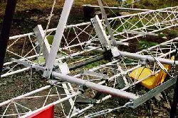
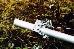
I am using 30'-2" long aluminum vertical
masts for the yagis (constructed by using a center 20' long
piece of 2" IPS schedule 40 6061-T6 PIPE, with 2" 6061-T6
TUBING, .125" wall, telescoped 11" inside it to lengthen
each mast end an additional 5'-1"). These vertical
mast materials are very stout and are standard sizes,
available through most any supplier of aluminum. The 2"
tubing fits quite easily inside the Schedule 40 Pipe (with
.070" clearance), and a round shim for each of the
four 12" long overlapping joints was made by forming a piece
of 6.25"x14"x.020" aluminum to fit between the two
members. Each joint was then bolted using two
3/8" hardened steel bolts and washers, oriented orthogonal
to each other, and located 3" in from the end of each member
(5" between the bolts).
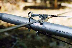
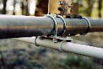
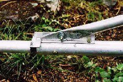
The masts are rigidly braced from the center to the midpoints with 1.5" aluminum tubing, and also guyed out to the antenna mounting locations with 1/8" steel guy wire (supported by a 4' long length of 2"x2"x.125" aluminum angle, and supported with 1"x1"x.0625 wall square aluminum tubing). One of the mast splicing bolts was used, in conjunction with a U-Bolt, to secure the mounting bracket for attaching the rigid bracing. The masts are also braced sideways (at the antenna mounting bracket points) with Phyllistran cable. The masts were mounted so that the center of gravity the mast (when both upper and lower antennas with feedline attached) was in the center between the two horizontal towers. The horizontal framework is a "Double H frame" using a total of eight 8' sections of Heights AC14-100 aluminum tower (for two 32' long towers), spaced approximately 2' on center from each other. I used a single 48' long piece of this in my 16 yagi 2m array, and it worked fine, but twisted slightly. The double H frame using that material, when properly guyed and supported, is far superior, very lightweight, and more than adequate (this array only weighs half as much as my 2m array). The length of the pair of assembled aluminum tower sections is actually 31'-8". The centers of the masts were each mounted 4.75" in from each end, with the antennas mounted on the outside of the masts. This resulted in a horizontal stacking distance of 31',4-7/8" between antenna centers, which was very close to the targeted 31.5'. In the center of the array, 4" aluminum channel is run
diagonally above and below the two horizontal towers, onto
which the 1-15/16" pillow block bearings from the
elevation mount are bolted. With this configuration
of the double H frame and diagonal mounting, the center of
gravity and pivot point is exactly in the center of the
array. The entire properly balanced array is very
easily elevated. A photo at the left shows one of
the pillow blocks bolted onto the central elevation shaft
(as viewed from below after the antenna was installed on
the mount). Additional close-up photos of the vertical
masts and the tower cross booms are also shown. As is more apparent after the antenna is in the air (photo at lower right), the upper horizontal tower of the H frame assembly is mounted to the rear of the vertical aluminum support masts. The lower tower is mounted to the front of the vertical masts. There are a pair of 5' long vertical aluminum masts similarly mounted between the two towers (immediately adjacent to the central support channels) used to support the 3/8" heavy duty Phyllistran cables from the center of the array out to the ends of the horizontal members of the H frames (to prevent sagging of the H frame when the array is pointed at the horizon). The array is also braced out the front, from a center point with cables running out to the end of each bracket where the tower is attached to the main vertical masts (to keep the frame from sagging when the array is elevated). As shown in the bottom photo at the left, the weighted precision 3 turn elevation potentiometer that is used for elevation readout is mounted in a pair of metal film canisters. Nylon cable ties hold the assembly inside the lower tower section next to the mount. |
|
| THE ANTENNAS | ||
|
Side-to-side bracing is provided to prevent
the yagis from flopping over while elevated, although
subsequent builders of this same array have not found this
necessary. This bracing was done through the use of
1/8" diameter Phyllistran cable, run just underneath the
elements on each yagi, from the boom to a fiberglass cross
member mounted near the center of each yagi. The 8'
long pieces of fiberglass poles were cut from broken pole
vaulting crossbars (acquired through the courtesy from The
University of Montana track and field athletic
department). Plugs were put into the ends of the
fiberglass poles so the U bolts holding the angle aluminum
mounting brackets (for the Phyllistran cable turnbuckles)
would not crack the fiberglass. The plugs were
standard nylon fittings for bed casters (there is quite a
size selection of these at the local hardware store).
The fiberglass poles were lightly sanded, cleaned, and
painted with three coats of white paint formulated for use
on fiberglass (expensive, but also available from the local
ACE hardware store). The paint used was "Marine Topside
Polyurethane Enamel" by Valspar Corporation.
The antennas came with dacron ropes to support the booms
from a temporary 24" high central support post that needs
to be clamped to mast after the antennas are
mounted. Galvanized 1/8" steel guy cable was
substituted for the dacron line, and 25.75" long pieces of
1.25"x1.25"x.125" square aluminum tubing were bolted to
the small guy support on each of the top two yagis.
This extension of square aluminum tubing (weighing 1.35
pounds) makes a tight fit extending 4.25" down inside
(past the top three mounting clamps - see photo) the tops
of the round 2" masts (1.75" ID), and provides adequately
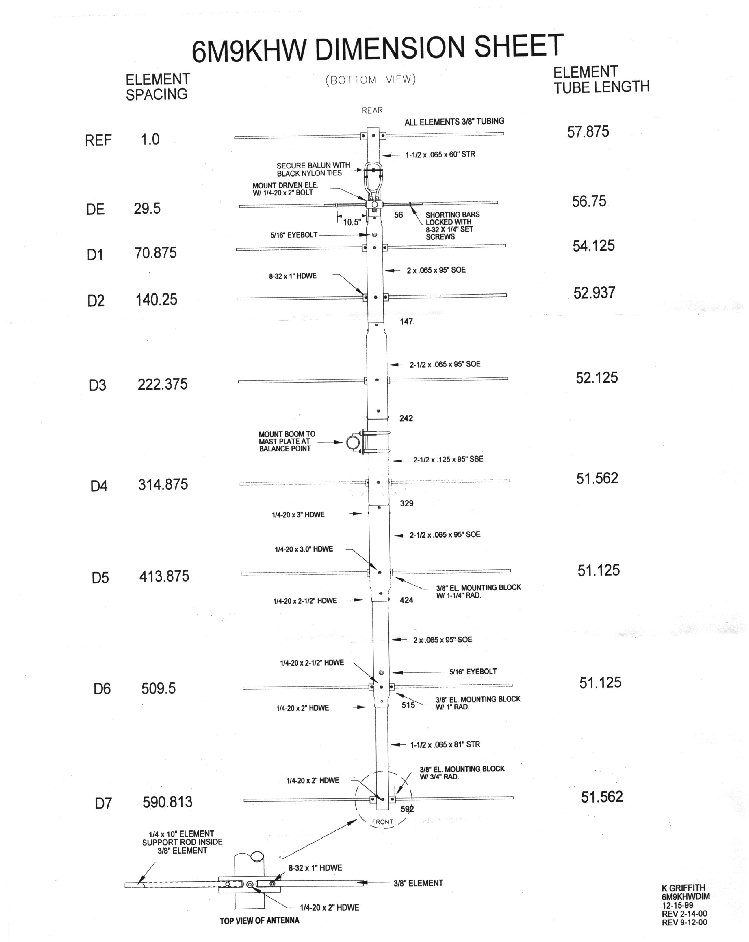
stiff, permanent support for the boom guys. The correct M2 T match and mounting block assemblies for
the driven elements are 25" overall length (the T match
rod extends out 11.5" on each side of the machined
connector block). I mention this only because it is
not mentioned anywhere in the assembly directions or
specifications sheet, and I initially had no idea that all
four of mine came to me the wrong length. I cut them back
to the lengths mentioned above, and secured the shorting
bars to the driven element (at a distance 10.5" from the
edge of the connector mounting block to the center of the
shorting bar). When mounting the shorting bars, I
first put "permatrox" on the aluminum-to-aluminum
connections, and coated the shorting bar set screws with
Locktite. All the coaxial connections and places where
penetrations are made to the machined connector block are
sealed with non contaminating silicone caulking. NOTE: More recent M2
6M9KHW yagis have been manufactured using a split dipole
with a hairpin match. The balance point for the yagi of course depends on the particular feedline and support systems used. For my yagis, the balance point was 20'-1/2" from the end of the N connector on the DE feed block. By bending the feedline away from the mast at a point 30" from the center of the yagi, approximately 19' of LMR feedline weight is added to each yagi. The completed, trussed up yagi (less feedline) weighed in at approximately 49 pounds. |
|
| RF CABLING | |
| The 50 ohm phasing lines were constructed
from LMR600 cable. The length of each line (with
connectors installed) was 42'-7.5", which corresponds to
2.5 wavelengths at 50.150 MHz (0.2
dB loss). This was confirmed by the short
shown by sweeping the open feedlines at 25.075 MHz
(where the length is 5 quarter wavelengths). The
weight of each completed phasing line with connectors was
approximately 5.83 pounds, approximately 2.6 pounds of
which was on each yagi..
With the extra electrical lengths inside the power divider and the two N chassis connectors, it was estimated that the actual overall length would be 2.5 wavelengths just under 50.100 MHz. The 4 way 1/2 wavelength power divider was built from
1.25" OD square aluminum tubing with a .125" wall
thickness. The inner conductor was 15/32" OD round
hobby brass tubing, creating a line impedance of 50
ohms. Four .375" thick teflon spacers were evenly
spaced at approximately 20" intervals (between the
spacers or RF connections) through the inside of the
square tubing, to keep the center conductor supported
and centered. The overall length of the aluminum
tubing for the power divider was 10', with 57.75" (using
a velocity factor of .98) from the center connector to
the point where each pair of N connectors were
connected. (Next time I suggest using a velocity
factor of .975, since the low end of the 6m band was
just on the upper end of the bandwidth for a perfect
match with the device built as described
above). The estimated loss for half of
the power divider is less than 0.02
dB. The connector for the main feedline
was a 7/16 connector, to insure plenty of extra
durability in terms of handling RF power. The
flexible coax around the rotator was LMR600 ultraflex,
with 7/16 DIN connectors on both ends (0.1 dB). |
Initially, 3/4" diameter 75
ohm CATV hardline was used for the feedline, which
required an impedance transformation. This was
achieved by constructing an "L/12" impedance transformer
and mounting it at the top of the tower. The
transformer was designed around 1.25" OD (1" ID) square
aluminum tubing (the outer conductor, sized to accomodate
the connectors selected), with appropriately sized hobby
tubing to construct the required 50 and 75 ohm
sections. The 75 ohm section (toward the 50 ohm
antenna) was an 18.75" long piece of 5/16" diameter
tubing; the 50 ohm section (toward the 75 ohm feedline)
was an 18.75" long piece of 15/32" diameter tubing.
A single teflon spacer was used at the center where the
tubing sizes changed. At the antenna end (to
connect to the 50 ohm LMR 600 Ultraflex), a 7/16 DIN
female chassis connector was mounted to the square
aluminum tubing of the transformer. On the feedline
end (to connect to the 3/4" CATV 75 ohm hardline), a male
HN connector was mounted to the transformer. The
feedline to the shack is 200' long.
In the shack, a traditional 1/4 wavelength long coaxial
impedance transformer (of 61.5 ohms) was used to convert
the 75 ohm CATV hardline back to 50 ohms. I constructed
mine from 1" "Type M" copper tubing (OD=1.125",
ID=1.055), with a 57.6" long piece of 3/8" OD hobby
tubing as the center conductor. The 75 ohm CATV hardline was later replaced with 1-5/8 Heliax and the impedance transformers at both ends of the feedline run were bypassed. Total loss for the 200' of Heliax (with 7/16 DIN connectors on both ends), is 0.4 dB, resulting in less than 0.75 dB total line loss to the low noise preamp in the shack. |
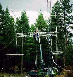
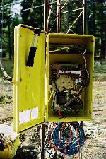
| ARRAY ASSEMBLY | ||
|
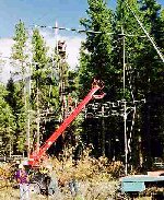
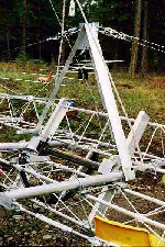
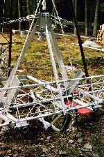
The H Frame was first raised up and hung
against the tower so the bottoms of the vertical masts
just cleared the ground. Even so, the sign company
ladder truck could not reach up high enough to raise the
antennas up to the tops of the top of the masts (around
32'). Therefore a crane was used to raise the
antennas into place, and the bucket on the ladder truck
was used to stand in and reach up to tighten the
boom-to-mast clamps on the upper antennas.
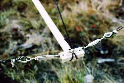
The lower antennas of course were within easy reach of the ground, and were mounted by hand. The crane was then used to raise the complete array up to the top of the tower, where the H frame was bolted to the pillow block bearings on each end of the central support shaft of the elevation mount. Power supplies to run power the elevation and prop-pitch motors, along with relays to enable actuation from the house, were enclosed in a waterproof plastic box mounted on the bottom of the tower. A messenger cable (low to permit clearance of the yagi reflectors when the array is pointed up at the moon) carries the feedline , AC power cord, and 8 conductor control cable from the house. The main tie-down ropes are 4 nylon lines attached to
the center of the two vertical masts. "S" hooks
were also mounted in the bottoms of the masts so 4 more
secondary stabilization lines could be easily hooked on
(by reaching up with a 15' long aluminum pole) when
especially severe winds are anticipated. From
experience with my 2m EME array, it was found that tie
downs attached only to the central horizontal boom do
resist winds trying to rotate the antenna in azimuth,
but the "rocking" effect from forces acting on the
elevation mechanism can completely destroy the coupling
there. By also using tie-downs on the bottoms of
the masts, such forces acting against the elevation
mechanism can be limited. A more detailed description how how the array is tied
down (excerpted from the overall W7GJ 6m EME Station
Operation manual) is HERE.
|
|
| PERFORMANCE | |
 |
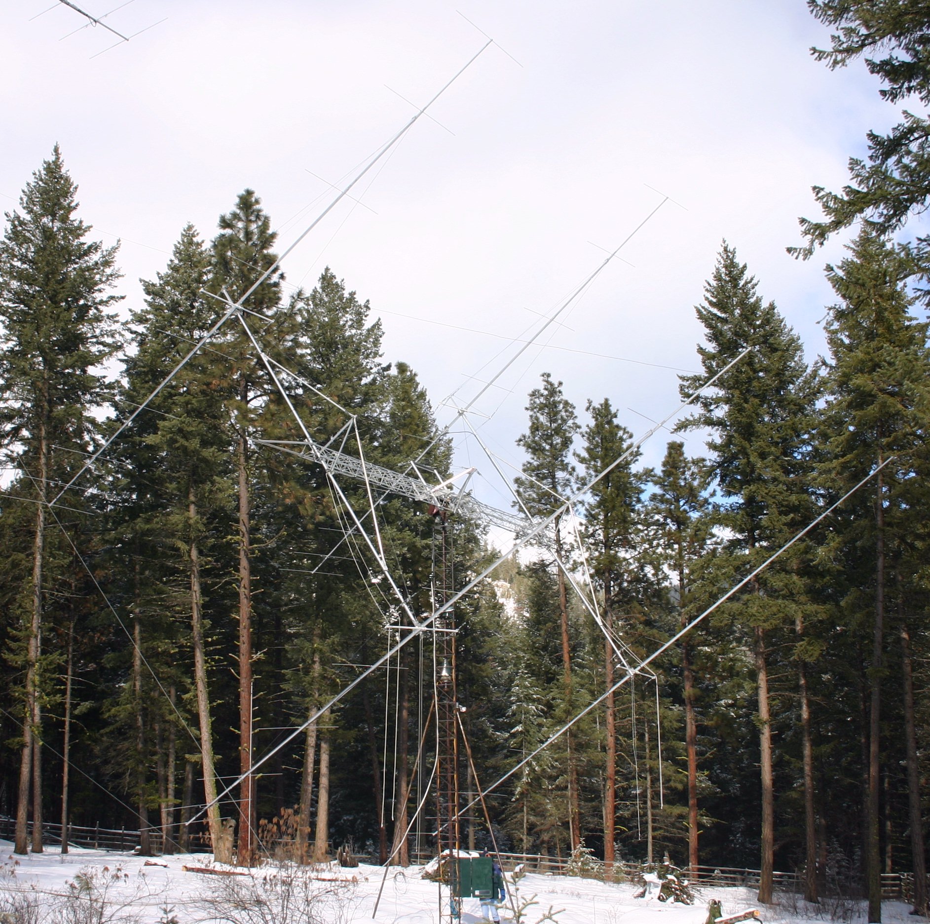
The VSWR of the antenna is nearly perfect between 50.100 and 5.200 MHz, showing only a few watts reflected with 1500 watts forward. During the first weekend of testing, echoes off the moon were present over half the time, and moonset signals from the 9G5AN DXpedition in October 2001 were detected on almost every transmission they made. The charts at the top of the page indicate a beamwidth of about 10 degrees down to the 1 db point; although this may seem extraordinarily sharp to 6m operators used to being able to watch a very wide range of azimuths for incoming DX signals, it sure seems very comfortably broad for EME (at least compared to my 16 yagi array on 2m)! Before I had the indicators and remote controls set up, I was limited to visual aiming, and I confirmed that the antenna seemed to work fine as long as I went out to move it every 30 to 45 minutes! Even pointed through the trees at moonrise, echoes are quite good, and the antenna seems to perform noticeably better than the single 70' long yagi at the 70' height, at least between 90 and 235 degrees azimuth. Aiming the antenna at northern cold sky produces a noise of 2.5 dB, compared to a 50 ohm load here in the shack. More testing will be necessary to confirm, but the
initial comparisons show that the single yagi works
better in directions (such as Japan), where the lower
yagis are essentially at ground level within a dozen
wavelengths, due to local topography. In other
directions in which the EME array has a clearer shot (
such as toward the Caribbean), the EME array is clearly
a better performer. A chart
of the horizon provides a more complete
picture of some of the VHF challenges of living in the
northern Rocky Mountains! The antenna is
normally tied down at 110 degrees, which is aimed at
Missouri (1xEs), Georgia (2xEs) and eastern Caribbean
(F2). It has been very helpful to use the
single big yagi at 70' to locate DX stations, and then
bring the GLEAP array around to the proper azimuth when
a few extra dB is necessary. Hope to contact you
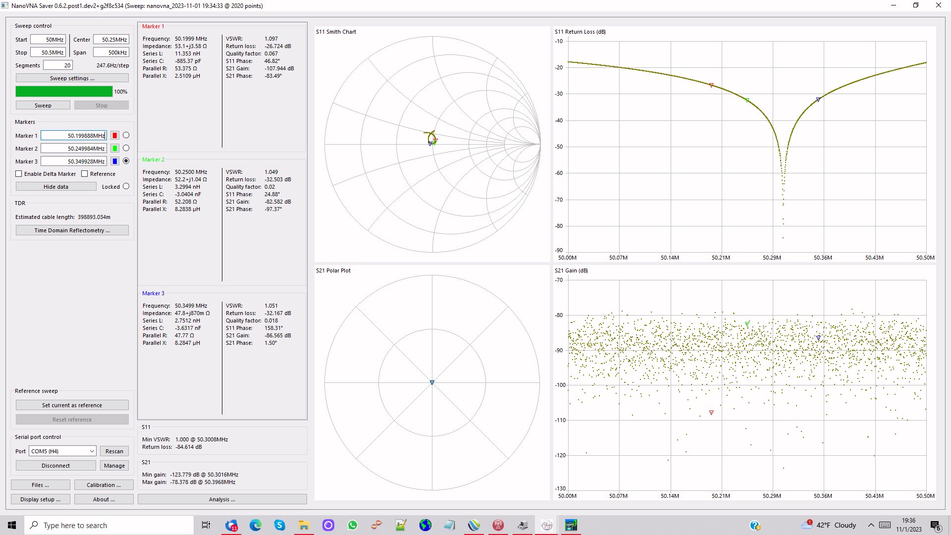
with it soon! As you can see from the NanoVNA plot below, the best match of the array is at 50.300 MHz. |
 |
Most recently updated on 3 November, 2023
![]()
