 Motor housing with new motor attached, ready to be raised up into place on the tower. |
In January, 2011, the
"medium size" prop pitch motor on my 6m EME array failed
to
operate. I suppose the problem was that the
brushes were worn out
and the motor was covered in oil that leaked from the
gear
housing. I could have had the motor repaired, but
decided that it
would probably continue to be damaged by leaking oil
from the bad seal in
the gear housing. I was not interested in removing
the entire
prop pitch motor for complete rebuilding, as the cost
was beyond my
means and I could not afford to have the array non-
functional for an
extended period of time. The solution I chose was
to simply
purchase a new Leeson sealed 1/4 horsepower 24 VDC
reversible motor and
attach it to the prop pitch gear assembly via the shaft
that extends
out of the bottom of the original prop pitch
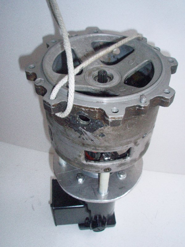
motor. My first attempt was to mount the motor on a bracket in the tower, and connect it to the old motor shaft. However, I was unable to align the two shafts well enough with that arrangement, and there was a tremendous amount of vibration when I ran that system. After a few days, I decided I needed to figure out how to mount the new motor directly onto the prop pitch motor housing itself so the shafts would be better aligned. After talking with the "Prop Pitch Guru", K7NV, I learned that the motor housing could be removed from the gear assembly without having all the gears fall out onto the snow ;-) So, emboldened by our conversation, I removed the entire motor assembly, which is held onto the prop pitch gear section by (8) 1/4-28 bolts. The photo to the left shows the top of the motor assembly after it has been removed from the main gear housing assembly. You can see that there is a top plate which holds the top bearing for the hardened motor shaft, which has splines machined in the end of it to plug into the main gear box. This top plate simply lifts off the main motor housing when the assembly is removed from the gear box, and then exposes the motor shaft and the motor windings. These precision aluminum castings are really a thing of beauty and fit so perfectly, it was great to be able to use them! With the help of AJ7LL and his machine shop, we removed all the field windings and all other connections that were attached to the inside of the motor housing. The grease and oil could then be removed from the motor housing. The shaft with its windings and upper and lower bearings was kept intact and reinserted into the cast housing. With the field windings removed, there was plenty of clearance above four existing 1/4" holes in the bottom of the motor housing. This allowed me to insert 1/4-20 x 4" stainless steel bolts down through the holes from the inside of the motor housing. You can see the head of one of those bolts in the photo to the left if you look through one of the openings in the aluminum housing. |
| The exposed old motor
shaft
was 5/8" diameter and had a 1/2" threaded portion on the
end. The
threaded portion and approximately 1/2" of the 5/8"
shaft was cut off,
so a shaft coupler would fit relatively closely to the
bottom of the
old motor housing. The flexible shaft coupling
comprises a
section that is bored for a 5/8" keyed or flatted shaft
interlocked via
a rubber insert to a mating coupling to fit on the 1/2"
shaft of the
new motor. 1/4-20 screws were tightened down on
top of the set
screws in each half of the flexible coupling so the
couplings' Allen
set screws could not work out. 1/2" OD nylon spacers for 1/4" bolts were purchased at the local hardware store. Two 1" spacers and one 1/2" spacer were used on each bolt, along with three galvanized washers, as shown in the photo to the right. These provided the proper spacing for an almost-tightly fit coupling between the motor housing and the new motor mounting plate. The mounting plate for the new motor was cut out from 5/16" thick aluminum. The bottom of the old motor housing was used as a template to mark the outside diameter, center hole, and the four holes for the 4" long 1/4-20 mounting bolts and spacers. The motor also mounts to the plate with four 1/4-20 bolts so that the motor shaft is exactly in the center. The motor mounting bolts were located in between the spacer bolts, as shown in the photo. Nylock nuts were used on the bottom of all 8 bolts. The whole assembly was bolted back up onto the bottom of the gear housing with the original 1/4-28 bolts and washers. A 15" high section of thin sheet aluminum was wrapped around the entire motor assembly to keep out rain and snow. The control circuitry at the base of the tower was reworked to reverse the motor leads going to the motor for changing between CW and CCW antenna rotation. A 20' long cable with a pair of 10 gauge stranded wires provides the DC voltage up to the motor. A heavy duty transformer in a large waterproof plastic cabinet at the base of the tower provides around 15 VDC from a full wave bridge rectifier without any filtering. The new motor and prop pitch gear assembly run very smoothly with no noticeable vibration. Even at that reduced voltage, more than enough torque is provided to turn the 6m EME array. 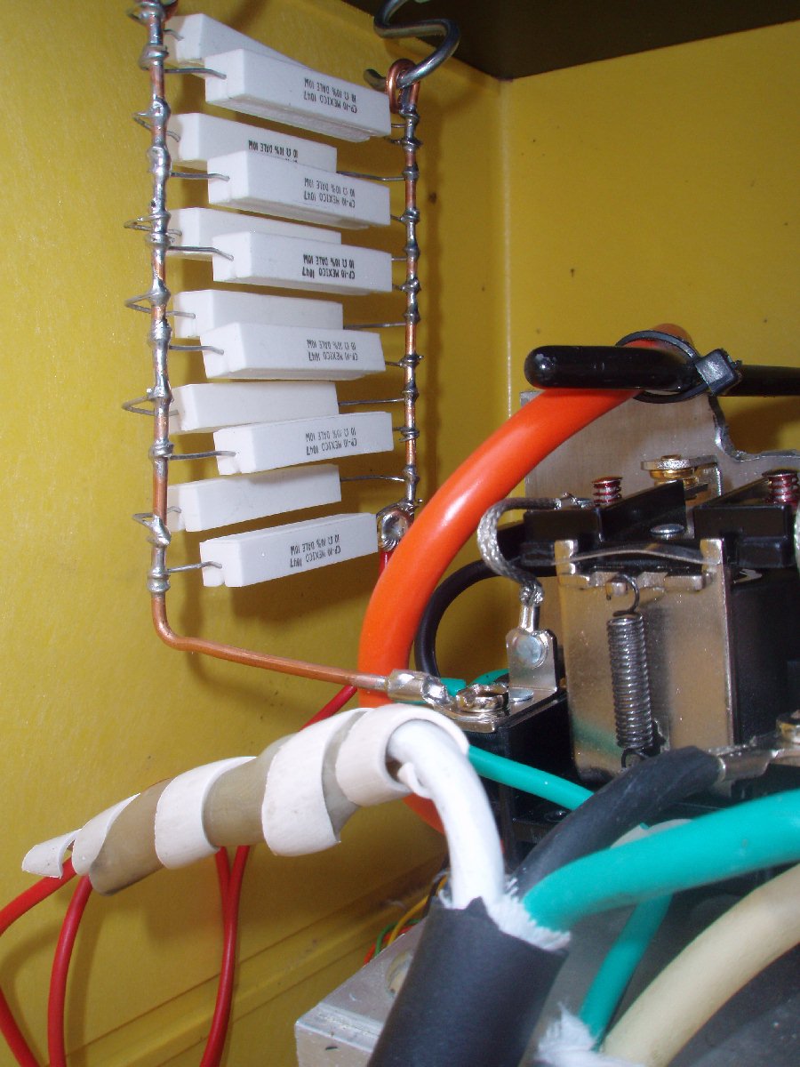 Closeup of the resistor
bank
installed in the motor control box at the base of the
tower.
|
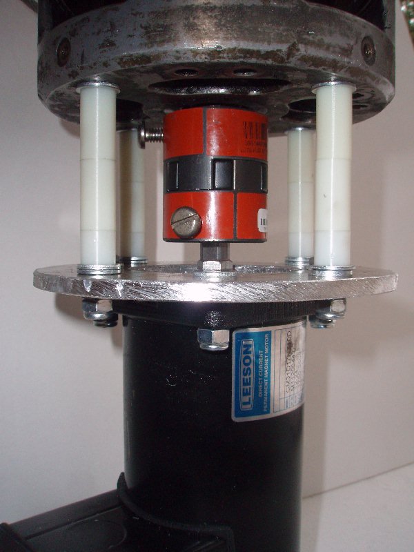 Closeup of the spacers attached between the old motor housing and mounting plate for the new motor In order to slow down
the
initial speed of rotation, and make it
possible to "fine tune" the azimuth by making small
quick adjustments
clockwise or counterclockwise, a resistor bank was
added in one of the
power leads to the DC motor. Twelve (12) 10 ohm,
10 watt
wirewound resistors from Radio Shack were soldered up
in parallel to
provide a voltage of only a few volts when the motor
starts up (drawing
maximum current). Once the array starts moving,
the current goes
down, the voltage drop decreases, and the resistor
bank does not have a
significant retarding effect on the speed. The
motor operation is
now very smooth and controllable.
|
Copyright 2011 - 2012 Lance Collister
Last Revised 24 January , 2012
![]()