from W7GJ for use on 50 or 70 MHz
For easiest viewing of this page, it is suggested to use Internet Explorer (which automatically resizes the page for your monitor) or simply hit the VIEW/ZOOM OUT tab a few times at the top of your Firefox browser. This page is divided into seven sections:
1. General Overview of the amplifiers
2. Power supplies to run them
3. Addition of cooling fans
4. Use of coaxial relays to switch them in and out of the circuit on transmit
5. Construction of a low pass filter for use with these amps
6. Optional information on combining two of these amps for increased ruggedness
7. Prices and ordering details
8. Photos of what some other 6m hams have done with them
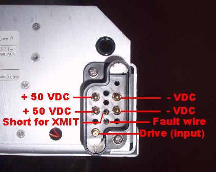
 Front of Harris Platinum I amplifier module showing the fault lights |
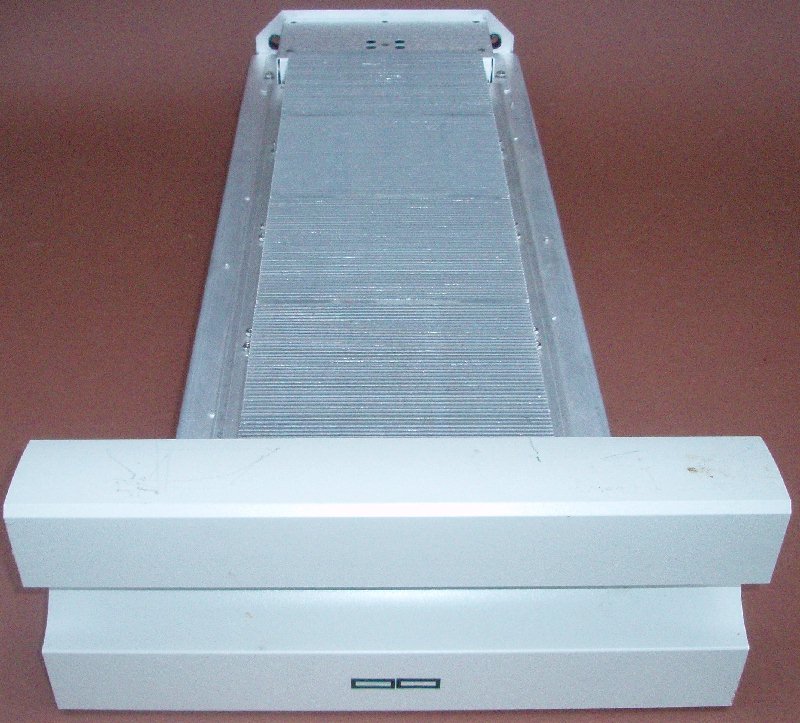
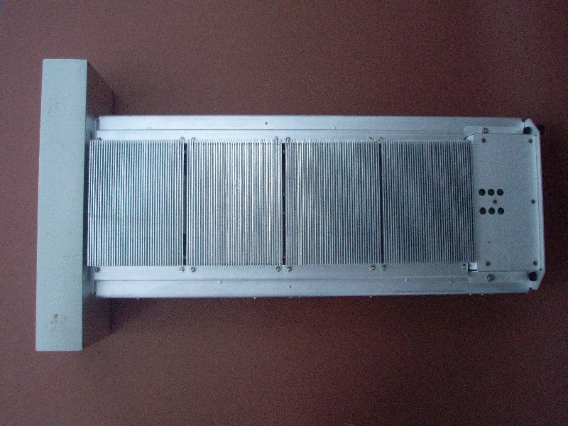 Top of a Harris amp
showing the four 6.5" wide by 5" long sets of
cooling fins requiring the addition of cooling
fans Top of a Harris amp
showing the four 6.5" wide by 5" long sets of
cooling fins requiring the addition of cooling
fans to suck air up away from their tops and sending the hot air away from the amp. This also pulls incoming cool air through the side holes, cooling the input and power divider circuits inside the amplifier, which is then exhausted through slots in between the sets of heat sink fins shown above. |
These very reliable Harris Platinum I amplifier modules were removed from service when VHF TV transmitters in the United States moved to digital transmissions in the UHF spectrum. They were working when removed from service. Although they use special OEM transistors, they have excellent protection circuits built into them, and should last a long time at amateur power levels if treated properly. Make sure that you do not operate the amplifiers into a high SWR, do not apply voltage spikes above the recommended voltage limits for the units, and do not overdrive them. Many inexpensive ham transceivers (particularly ICOM) produce RF output spikes at full power, and such drivers may damage these amplifier modules. It is advisable to limit the drive power to around 10 watts maximum. Typically, 10 watts drive typically produces between 800-1000 watts output on 50.200 MHz (drive between 22 and 28 watts produced a maximum around 1400 watts output on the Channel 2 amplifiers I shipped). Obviously, if you drive the amp over 1000w, you need to be careful not to overheat the amp or the power supply. As they come, the amps are Class A and are not biased for peak efficiency. Also note in the Cheese Bits articles below that the displayed output will drop somewhat after the amp is run through an effective 50 MHz low pass filter, which will need to dissipate a fair amount of power to remove the harmonics!
Excellent documentation on the use of these Harris Platinum I amplifiers as ham radio amplifiers on the 6m band has been prepared and is available here. Additional excellent documentation of these amps was provided by KB3XG in a three part series published in the the May, June and August 2010 issues of "Cheese Bits", the official newsletter of the Mt. Airy VHF Radio Club in Southampton, PA. I have excerpted those three Cheese Bits articles and combined them into a single convenient PDF file. I also have provided a convenient summary of the amplifier FAULT CODES. I urge you to read through all these before firing up the amplifiers. I am providing these links and the information below so the experienced 6m operator will be able to construct his own station utilizing these amplifiers. You also may find this Harris Trouble Shooting Manual helpful if you run into trouble not discussed in the above links.
The dimensions of the unmodified amplifier modules are 15" wide x 6.25" high x 27.5" long, and they weigh 29 pounds. The dimensions of the amplifier behind the front panel are 4.4" high x 10.5" wide x 25" long, and the heat sinks are 6.4375" wide. Please also remove the bottom cover and remove any bugs (that could short about components) or paper inspection labels that may have fallen into the inside of the amp (they may block air openings, causing overheating).
NOTE: Apparently one of the most common problems with the amps is that the old heat sink compound dries out and turns to dust, resulting in a burned out transistor module when the amp is in use. So you may need to check to make sure the heat sink compound between the transistor and the heat sink is still good, and/or replace the heat sink compound before firing up the amp.
These amplifiers are not completely "plug and play" and are recommended for experienced and licensed ham radio operators only. They do not require any electrical modifications to work successfully on 6m. However, they DO require some mechanical connections and external additions; you must make the real panel power connections, and add RF input and output connectors - unless you purchase the special Harris RF connector cable and Power Connector. Users also will have to provide their own way to switch the amplifier in and out of the RF circuit using coaxial relays, ground the amplifier PTT line to enable it on transmit, provide a power supply capable of providing a minimum of 40 amps between +44 to +54 VDC , add cooling fans to the heat sinks, and provide a low pass filter. Some suggestions regarding these additional items are provided in the references above, as well as discussed below for consideration, but no responsibility is assumed for any such items or how they are used.
Please do not expect further support or individual assistance from me. I will not warrant the performance of these amps after they leave my location, although I have tested each of them before shipment. If any part of this sounds too complicated to you or you have any questions about it, these amplifier modules are NOT FOR YOU. At these low prices, I cannot afford to provide any additional service or support - they are being made available to you at such a reasonable price because I am interested in helping stations here in North America and overseas to get on 6m with some power, and I am assuming you know what to do with them!
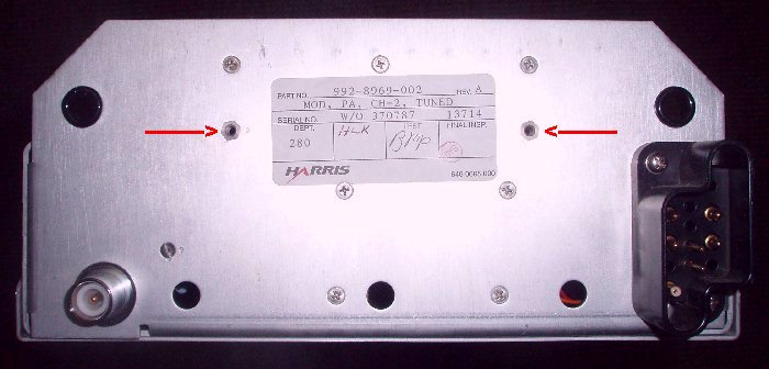 |
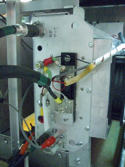
In
the photo to the left, please notice that
the two 6-32 threaded inserts are spaced precisely
to match the mounting holes in the SNT-50 Meter
shunts referenced in Section 2 below. One
can be mounted very conveniently on the rear of
the Harris amplifier by using two 6-32 x 1" long
screws, with washers and lockwashers. The negative DC line going to the
amplifier can then be run through the meter shunt
to ground so the current can be displayed by
measuring the voltage across the shunt. Perhaps a better option for measuring the current is to simply run the B+ lead through the opening in one of these LEM Current Transducers and measure the output current with a 50mA meter to correspond to an amplifier current of 50A. (Actually, I rarely watch the current on mine anyway - I find using a wattmeter to watch the output far easier and more useful.) |
 |
| Please
refer to the documentation referenced above
to re-route the rear panel connections in the
event you do not have the special Harris
connectors for the RF and DC power/RF drive
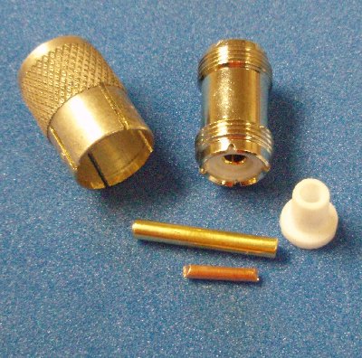
plugs. I did find a very convenient way to
make an adapter for the special Harris RF output
connector, so the Harris chassis connector itself
did not have to be removed or replaced. To
make an adapter to a female UHF type connector, I
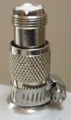
used the following pieces: 1. 5/32" OD brass hobby tubing, 1.1" long to make a new connector center pin. 2. #10 solid copper wire, 1/2" long. 3. UHF female-female barrel adapter 4. Outer shell from a PL-259 male UHF connector, with the lip reamed off the rear, and four slots cut halfway down the connector (to the point where the threads start) with a hack saw. 5. A teflon center section (1/4" OD) from a male HN connector, cut back to a total overall length of 1/2", and the center pin hole enlarged using a 5/32" diameter drill bit. You could also make it from a 1/2" long piece of 1/4" diameter teflon rod. You probably don't really need this part, but it sure works great with the Harris connector! The
tip of the center pin of the Harris connector
was tinned, and then the copper wire was slipped
inside the the 5/32" OD brass tubing, which was
slid completely down over the center pin of the
Harris connector. All three of those parts
were then soldered together, and the teflon plug
was placed over the new center pin.
Finally, the PL-259 outer shell was threaded
onto the barrel connector far enough so that the
outside of the barrel connector bears against
the Harris connector when the PL-259 shell is
resting against the Harris connector flange on
the chassis. The PL-259 shell is then
secured at the slots with a stainless steel hose
clamp.
Remember to carefully vacuum out any aluminum scraps from the drilling or reaming that you do! You want to keep the inside free from any stray bits of aluminum that could cause problems later! |
  |
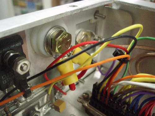
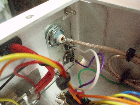 Inside view of
connections to plate replacing the plastic
connector
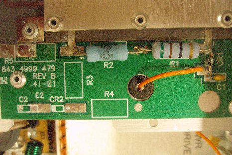 RF coupler with only
standard parts for reflected power sensing
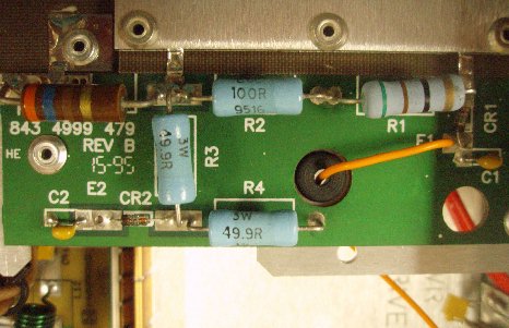 RF coupler with
forward and reflected power sensing parts -
a wire connected to point E2 provides
indication relative output or could be
calibrated to drive a wattmeter
|
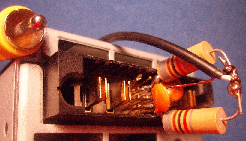
nstead
of using the special Harris plastic power and
drive connector, I replaced it with a small 2.75"
x 1.75" aluminum plate, which can be mounted back
on the amp using the same screws from the plastic
connector. I added a rubber grommet to the
existing hole next to the old connector, and
routed the two +50 VDC wires through the
grommet. The new aluminum plate shown now
holds a BNC chassis connector, and RCA connectors
for the Relative Power Output and PTT wire
connections. The black ground wires inside
the amp connecting the chassis to the old plastic
connector were removed entirely. Instead, a
hole was used for a 1/4" bolt that now provides
the connection for ground. (Just for your information, I did not
wind up doing anything with the Fault wire, so
in my opinion you might as well not bother even
bringing it out through the rear panel. If
anything goes wrong, the amplifier goes
out of XMIT mode, and the red LED blinks the
appropriate Fault code until you go back to
receive
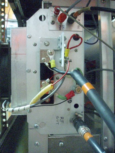
and re-set it.)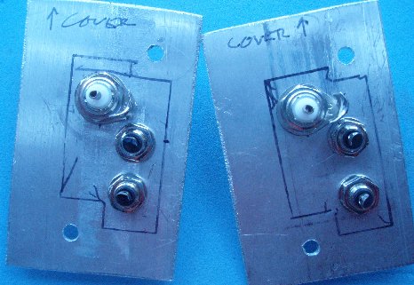 Two 2.75" x 1.75" x .0625" " thick aluminum plates fabricated to replace the Harris plastic power connector. Plates shown above have BNC connectors for drive input, and RCA jacks for Relative Power and PTT. You will notice there is an RF Coupler board next to the output connector, where the reflected power signal from the orange wire connected to point E1 is used to trigger a high SWR. If you have a board that is populated with parts (or you want to add duplicate parts to the other half of the board), you can also take off a signal from the coupler at point E2 to indicate relative forward output power. The Relative Power Output lead from point E2 can then also be routed to the new small rear panel plate, if desired. (Just for your information, I really don't use the forward relative power output lead here - I measure output with a separate wattmeter - so you may not want to bother even bringing it out through the rear panel either. I found that the forward relative power lead does give me around 150 mV reading across a 15 ohm resistor to ground when I am running about 750w output.) The photos to the right show the connections at the rear of the amp after they were mounted on their sides in a rack. Note that an additional RCA jack for the Relative Power output has been added. The red and white wires connected across the shunt are for the millivoltmeter to display the current being drawn by the amp. The shunt had to be installed in the negative lead of the power supply, to make the digital millivoltmeters happy. Notice that the fans (small black and red wires) are connected directly to the terminals for the incoming voltage and ground, so they will not add to the current being measured. The + 50 VDC is connected to a bolt mounted on a .125" thick piece of HDPE to keep it safely out of the way. |
  |
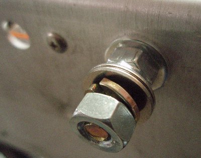
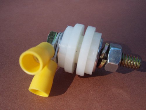 Basic concept of
the "nylon sandwich" feedthrough for the B+
 The "nylon sandwich" makes a very neat feedthrough for the B+ |
I also did the B+ feedthrough differently on several amps. I finally went down to my local ACE hardware store and bought some thick nylon bearings and nylon washers. Here is what I finally wound up with: (1) Nylon spacer 1/2" OD, 1/4" long, with a 1/4" hole in it for a 1/4-20 bolt to carry the B+ to the inside of the amp (2) Nylon washers, 7/8" OD, 1/8" thick with slightly more than a 1/2" hole in the middle. (2) Nylon washers, 3/4" OD, 1/8" thick with a 1/4" hole in the center. (4) Stainless steel 1/4" washers (1) 1/4-20 bolt 1.5" to 1.75" long (1) Stainless steel 1/4-20 nut (1) Split ring lock washer for 1/4" bolt (1) Nylock 1/4-20 nut If you ream out the current hole (next to the black plastic Harris connector) to 1/2" diameter, you can place the nylon spacer through the chassis, and there is still room for the 1/2" ID washers to catch on both sides of the chassis. The two red B+ leads inside the amp can be cut down after removal from the black plastic Harris connector, and 1/4" ring terminals soldered to them so they will fit under the head of the 1/4-20 bolt going through the nylon sandwich. Then put the 1/4" ID nylon washers on each side, followed by the thin stainless steel washers on each side. This makes a very nice feedthrough for the 51 VDC. I like to add a washer and Nylock nut on the outside to secure everything before adding the washers, split ring lock washer and regular nut for securing the power leads. |
 |
|
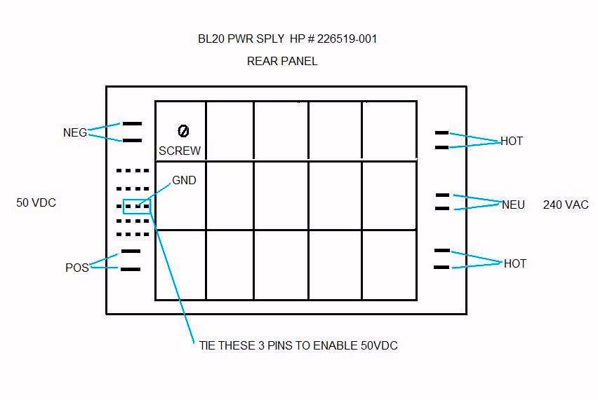
Units referred to as 48 VDC
"Blade Server" power supplies are readily
available on the surplus market and provide
a popular source of power for these
amplifiers. In particular, the Hewlett
Packard (aka Compaq) 3 kw BL20p switching power supply, often is
identified by its HP part number of 226519-001 and/or its spare part number of
253232-001. Here are
the specifications
for this particular power supply module.
They each weigh about 15 pounds, and are 2.75"
wide x 4.875" high x 22.25" long. They are
designed to provide a very healthy 57 amps of
power at 51.4 VDC. This voltage works
great with the Harris amplifiers.
These
power supplies have been reported to generate RF
noise (although I have not noticed it here), so
you should be prepared to ground the cases well,
and wind the output DC leads together around
suitable toroids with a ferrite mix that will be
effective at 50 MHz. Something similar to
the Palomar
F-140 Core with Mix 43 or the Fair-rite
Part # 2646804502
Mix
46 (what
I used here) should permit a number of bifilar
turns and be a good place to start. These
worked great for me, and I never noticed any
noise problems at all, but then again, my ham
shack is in underground in the basement, and
about 200' away from my antennas. If you
do have more noise problems, you may find it
helpful to shield the end of the power supply
and install chokes on both the AC and DC lines,
as OZ1LPR shows
here.
He reports excellent noise attenuation with this
construction. As
explained in the SECTION 1 above sited reference,
they also show you how to turn OFF the power
supply during receive periods if you encounter
too much noise. Basically, you only ground
the two outside pins of the three small pins
pictured above when you want to transmit.
They suggest bypassing those outer pins to
ground with a .1 uF disc capacitor to avoid
RFI. In the photo below, you can see one
of these power supplies prepared with each of
the two outer pins connected to the center pin
(ground) by .1 uF capacitors, and shorted
together with RF chokes. A shielded audio
cable with an RCA plug on one end then can be
grounded to activate the power supply during
transmit periods.
What I HAVE seen in noise tests here, though, is lots of noise from the USB and other cables connected to my computers when they are turned on! So, I suggest that all THOSE leads be treated with clamp-on ferrite RFI chokes first before worrying about the HPS3KW power supply! Newer commercial power supplies of course are available that do not have the RFI problems, as well as being lighter weight and more compact. A few sources you can investigate include Meanwell, Eltek-Valere, & Dongah Elecomm. |
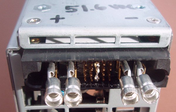 An upside down rear photo of one of these HPS3KW power supplies is shown above. Notice that the three lower center control pins have been shorted to enable the unit to operate when plugged into 230 VAC. Flat blade push-on spade connectors have been installed on the DC output leads and are shown ready for wiring. The photo below shows the power supply wired and ready for installation. Notice that the DC output wires have been bifilar wound on a ferrite core, and both sets of terminals are used for all connections. Neutral
is connected to the left two terminals, the two
center terminals are grounded, and 230 VAC is
connected to the right two terminals. If
you are like most of us in North America, they
also can be operated by connecting each of the
two opposite phase 115 VAC lines to the outer
two terminals (to provide 230 VAC between the
two of them) and grounding the center two
terminals. In other words, the center two
terminals are grounded and 230 VAC is applied to
the outer pairs of terminals. Notice that ground
from the wall socket is also connected to the
ground wire going to the amplifier chassis. 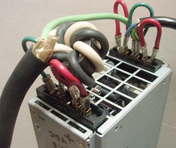 For those building up a station, All Electronics Corporation offers a shunt that can be installed in one of the DC power leads to the amplifier. The SNT-50 provides a voltage drop of 50 mV across the terminals when the power supply is providing 50A to the load. They also offer a meter that can be used to display that current. It is important to obtain a meter such as this that has independent negative leads for the power supply and the voltage to be measured. After connecting all my power leads, I moved the shunt to measure voltages near ground. Fortunately, the + and - leads from the HPS3KW power supply are "floating", so I was able to connect the shunt successfully between the - DC voltage and ground. I use an isolated 9 VDC "wall wart" to power the meters. The photo above shows how I brought the AC ground (green wire) over to the amps along with the filtered plus and minus leads. |
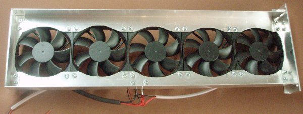
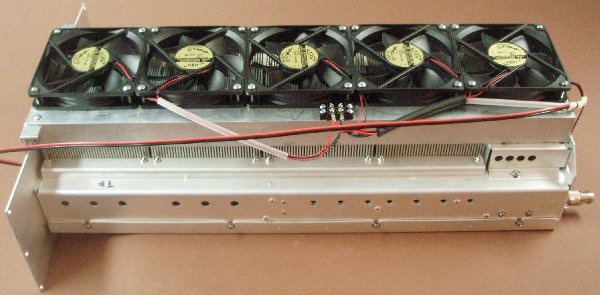
| It is necessary to add
fans to the heat sinks on these amplifier
modules. Inexpensive but high volume fans
can be mounted on top of the heat sinks to blow up
away from the heat sinks, as illustrated
in the documentation in Section 1 above. The
photos to the right shows five ADDA
AD1248-A71BL (99 cfm, 48 VDC) fans mounted
on 1/16" x 1.5" x 1.5" angle aluminum rails above
the heat sinks. These 5 units provide almost
twice the air flow recommended by Harris
for these amps, since I expect to be using
the units in JT65A mode. The angle
aluminum rails were scalloped out with a saber saw
and file, so as not to block the air passing by
the fan blades. The distance between
the top of the heat sink and the bottom of the
fans is 1.125", to allow plenty of space for
more even cooling of the entire heat sinks, as
well as the ability to suck up air through the
spaces at each end of the four heat sink blocks,
thereby also cooling the inside of the amp.
The standard large Harris front panel was removed to mount the fan assembly, as can be seen in the lower photo to the right. This was removed so the front end of the fan box could be attached to the small aluminum front panel rather than blocking the space between the front panel and the first heat sink - there is an air gap there (just like the gaps between each of the heat sinks) which needs to be clear to draw air up from the inside of the amp. The inside dimensions of the "fan box" were 6.4375" wide x 23.75" long. The heat sinks are 6.4375" wide, so the fan box fits very snugly over the top of the heat sinks. Notice that the 5 fans cover the ENTIRE LENGTH of the Harris amps! That is to make sure to provide cooling for all the amplifier modules PLUS the control module at the rear of the amp. NOTE: It is EXTREMELY IMPORTANT that you properly mount the fans and that they provide adequate cooling air IN THROUGH THE SIDE HOLES as well as IN THROUGH THE SIDES OF THE HEAT SINKS! Most of the failures that I have heard about are simply due to poor cooling. Test the sides of the heat sinks and the holes on the sides of the amp to make sure that a thin piece of paper is pulled in toward them. The above instructions on they type and number of fans and how to correctly mount them is VERY important if you want to avoid failures caused by overheating! A new front panel is being used to hold the indicator lights and current meters from a pair of these amps, which are being mounted on their sides (bottom to bottom) so the fans are blowing out each side of the rack in which they are mounted. |
  |
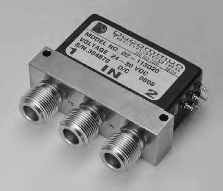
| These
Harris Platinum I amplifier modules are only meant
for transmit. Therefore, it is necessary to
switch them out of the circuit on receive, and
back into the circuit for transmit. It is
essential that they not be "hot switched" - that
the coaxial relays are finished switching before
the amplifier is activated into transmit mode, and
input power is applied. Typically, this is
assured by using "sequencers" to protect the
various components. In most applications, it
will be necessary to use a pair of SPDT coaxial
relays to switch the Platinum I amplifier in and
out of the circuit. The low power input is
made through a BNC connector and the high power
output connector is a type N connector.
Remember that each of these amplifiers is capable
of putting out 1500w or more on peaks, so a
quality relay with connectors capable of handling
that kind of power is essential. Often, quality surplus coaxial relays can be found at affordable prices on EBAY. Some relays such as the NARDA SEM123-N, or some of the DUCOMMUN D2 series (such as the one pictured here) even include pins for a built-in switch (so you can run your PTT line through it on its way to the amplifier, insuring that no power can be actually transmitted until after the relays have finished switching the amplifier in line. Proper sequencing is essential to extend relay contact life. If it is helpful, I have had some experience with Ducommun Model # D2-113D28 SPDT relays with N connectors. These work on 24-30 VDC, and latch in either position when there is a momentary ground on the coil for position 1 or 2. According to the charts, they look like they are rated for over 1000 watts average power at 50 MHz: http://www.bigskyspaces.com/w7gj/D2-113D28a.pdf http://www.bigskyspaces.com/w7gj/D2-113D28b.pdf http://www.bigskyspaces.com/w7gj/D2%20PowerChart.pdf A diagram showing how the above relays can be used to switch the amplifier in and out of the circuit is shown here: http://www.bigskyspaces.com/w7gj/DucommunRelayControlBox.pdf You can also build your own relays with good connectors that will handle plenty of power, and will work fine with very low VSWR on 6m. Often these can be built for less than the price of purchasing one or more commercial coaxial relays. Here is a home-made and easily duplicated DPDT coaxial relay design by WA4NJP that can be used to switch an amplifier such as the Harris Platinum amp in and out of the line between the transceiver and the antenna. Here are similar home-made high power 6m coaxial relays that I constructed. And here is a switchbox circuit I built to control these 24 VDC relays to switch a Harris amplifier in and out of the circuit: http://www.bigskyspaces.com/w7gj/HomebrewRelayControlBox.pdf |
 |
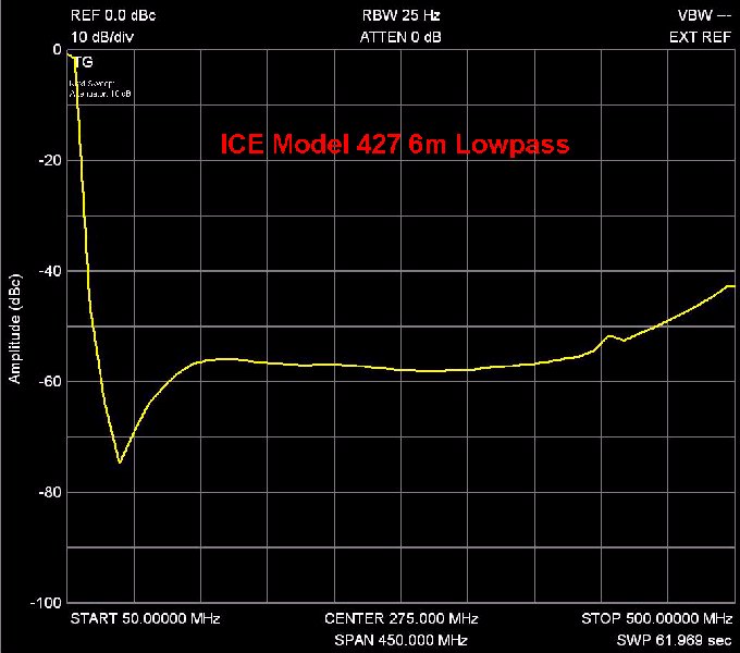
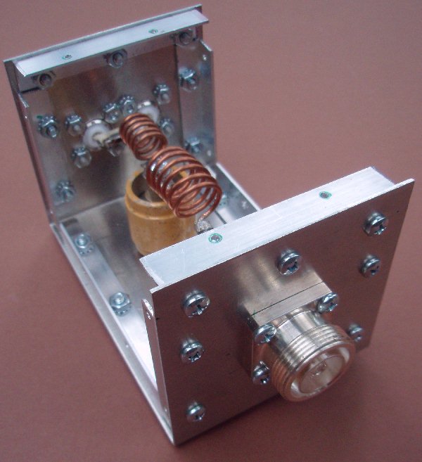
| To use these amplifiers in the United
States, it is necessary to install a low pass
filter on the output. The documentation
references Section 1 above describe the
construction of such filters. You can also
find plans for very good low
pass filters in ham radio
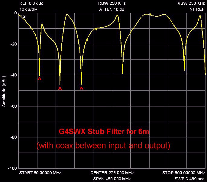
publications. You can also purchase commercial filters from Industrial Communications Engineers, Ltd. Their models 426 and 427 are especially effective for higher power levels, and afford up to 80 dB attenuation above 56 MHz, and close to 60 dB for higher harmonics. A plot of my ICE Model 427 is shown to the right. Here is another easy to build (although not as effective) QRO 50 MHz Low Pass Filter designed by K1WHS. The Type 857 50 pF 15kv doorknob capacitors for the K1WHS filter can be purchased from Fair Radio Sales or similar capacitors are available from Alex, UR4LL. Please see my FILTERS web page for additional ideas on effective 6m low pass filters. If you are unable to obtain the capacitors to built the above low pass filter or need additional attenuation, you may want to try a coaxial stub filter. Depending on how they are constructed, these are capable of handling quite a bit of power, and are very effective over narrow bandwidths. Since most of the DX activity on 6m is in a very narrow part of the band, using narrow bandwidth stub filters to short out the harmonics can prove to be a very effective approach on 6m. Information on well-matched and effective VHF/UHF open stub filters was prepared by G4SWX. The basic idea behind John's Coaxial Stub Filters is to keep the impedance (at the pass frequency, or 50 MHz) of the elements at the output port of the filter the same as at the input - hence you can match the whole filter by transforming the input impedance to its conjugate at the output. "The simplest filter of this type uses a quarter wave open circuit @2f on the input and open circuit quarter waves @3f and 4f on the output. This is a 'magic' combination because @f the impedance of the 2f stub is the same as the parallel combination of the 3f and 4f stubs. All that is needed is to transform the impedance at one end into its conjugate at the other". John suggests that the easiest
way to do this at high power is to use a coax
line rather than an inductor to do this
transformation. To construct a high power filter
using the above coaxial elements, John
recommends a quarter wave open circuit at
100MHz on the input and open
circuit quarter wave
stub at150MHz and 200MHz on the output. "Join
the input and output sections of the filter
together with a low loss coaxial line (0.265 x
velocity factor) wavelengths long. This
will give you >20dB return loss ( <1.2:1
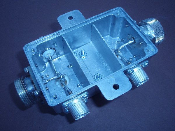
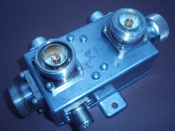
vswr) at the pass frequency." These photos do not show the three 1/4 wavelength open stubs (which attach to the teflon UHF connectors) or the .265 wavelength cable (which attaches between the two female 7/16 DIN connectors on the top of the box). For 50.150 MHz, the .265 wavelength high power cable between the filter input and output is a quarter wavelength long (so looks like an RF short) at 47.310 MHz. I used a piece of Andrew FSJ4-50 1/2" Superflex Heliax with 7/16 DIN connectors for that cable.
The quarter wavelength stubs for
the second, third and fourth harmonics were all
made from RG-213 coaxial cable with Teflon
PL259A connectors. Of course there were no
connectors on the open end - only plastic tape
covering the open cable. The coax was
trimmed using an MFJ Antenna Analyzer until it
looked like an RF short circuit at 100.3,
150.450 and 200.600 MHz. |
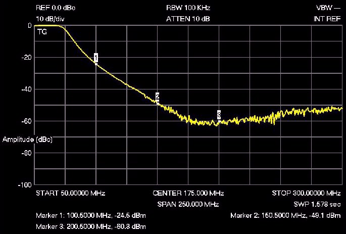
 These filter
performance graphs are courtesy of AJ7LL.
|
|
|
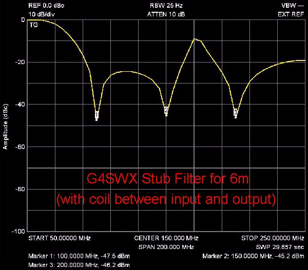 Harmonic attenuation of the stub filter using the coil. Second, third and fourth harmonics are attenuated between 40 and 45 dB. |
 |
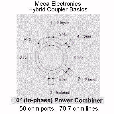
| Some
hams have combined two of these amplifiers to
provide 1500w reliable output for use on
continuous duty modes such as JT65A. If you
plan to do this, I suggest you research the
subjects of Wilkinson Power Combiners, Hybrid Rat
Race Power Combiners, and review the article on 50 MHz
Power Splitters from Issue 33 of UKSMG Six
News as a start in your investigation. The basic
configuration for a hybrid
combiner is shown in this diagram from Meca
Electronics; the port labeled as
"isolated" in the figure is where the dummy load
is placed, to absorb 50% of the power (maximum of
about 750w) from the remaining amp if one of the
amps shuts down. One
advantage of using the hybrid combiner above is
that when two amplifiers fed in phase, the second
harmonic is basically cancelled out when the two
outputs are combined. Combining a pair of
these amplifiers in this way, with the
additional filters discussed on this page,
produces an extremely pure 6m signal. During initial testing, I used a Heathkit Cantenna for the "dump load" at that port. However, the actual power going to that load with the setup described here was only around 0.1% of the 6m power output from the combiner/filter, so such a large dummy load was not really necessary for normal operation. I did find (per the Cheese Bits articles) that I had to slightly advance (approximately 1/8" turn clockwise) the small SWR potentiometer inside one of the the amplifiers to prevent it from shutting down when it was connected to the hybrid combiner and low pass filter. However, after the amps were properly operating, I found that it was a waste to have such a large dummy load tied up at that spot when such a small amount of power was going into the "dump load" port. If one of the amps goes offline while I am using it, either due to overdrive or high SWR, I would certainly quickly either stop transmitting and/or turn down the power to prevent the one amp from turning off. Therefore, a large dummy load really is not needed there for an attended amateur application during normal operating use. As a result, I eventually replaced the Heathkit Cantenna with the home-made 800w dry dummy load made from Caddock non-inductive resistors, shown at right. It is very capable of handling up to 800w for very short periods of time, and certainly can dissipate the small power that I measured at that port during normal operation. |
 |
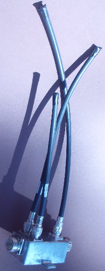
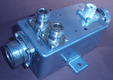
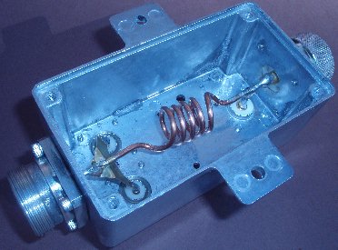
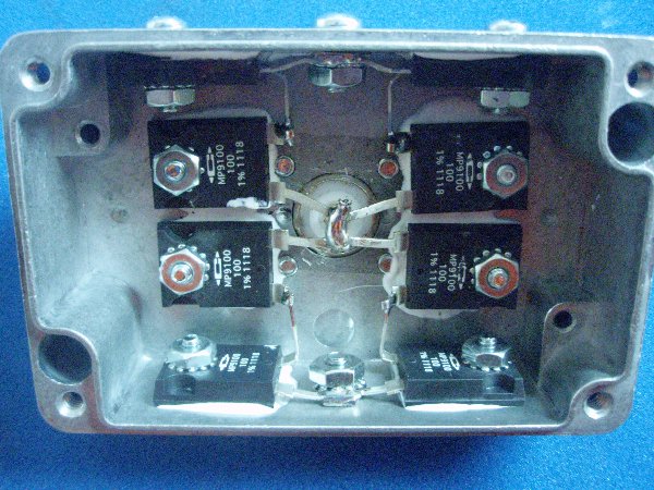
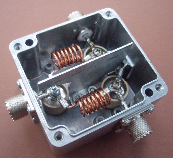
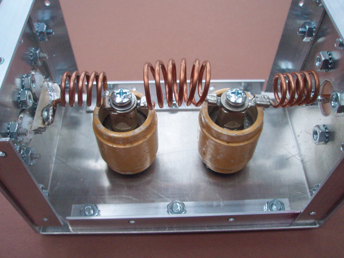
Using the UKSMG article above as a reference, a lumped constant Wilkinson Power Divider was constructed as a power splitter for driving a pair of Harris amps on 6m. A BUD AN-1319 cast aluminum enclosure was used for the project, with an isolation divider (constructed from some 1/16" angle aluminum) added down the middle. The input capacitor was the lowest value of a number of 100 pF type 850 doorknob capacitors I had on hand; the value was estimated to be around 96 pF, and it was used for the 90 pF capacitor called for in the article. Two other type 850 doorknob units (rated at 47 pF) were used where the article called for 45 pF. The 225nH coils were constructed by winding 7 turns of #14 awg wire on a 3/8" diameter form. The coils were each 3/4" long. The resistor was a Caddock MP9100-100 100 ohm non-inductive resistor, which was overkill for driving a pair of Harris Platinum I amplifiers, but I decided I wanted to over-build the unit just to be safe. You can see the Caddock 100 ohm, 100w resistor mounted on the back wall of the enclosure. This splitter was tested by verifying that when any two of the ports in this splitter are terminated in 50 ohm loads, the SWR is 1:1 on the remaining port. Since only low power is used to drive the amplifiers, equal lengths of RG-58U cable were used from the splitter (shown at right) to the BNC input connectors installed on the rear of the amplifiers. If you find that the amplifiers wind up slightly out of phase, the easiest way to make small adjustments is to add a right angle connector into one of the low power RF input cables (to slightly change the input cable length) and watch for a reduction in the power going into the "dump port" on the output hybrid combiner. |
 |
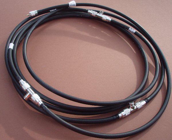 |
A
"rat race" hybrid combiner was built from coaxial
cable to combine the output of two of the Harris
amps. The design of the combiner calls for three
1/4 wavelength and one 3/4 wavelength 71 ohm
sections. I utilized Belden 8233 75 ohm
double shielded coaxial cable in place of the 71
ohm sections, because I had some on hand. I
joined the sections together using RFU534
UHF 'T' adapters with three female ports.
Good quality UHF connectors with teflon dielectric
were used on the ends of all the cables and at the
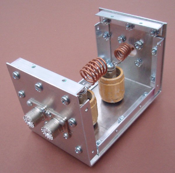
output combiner. I used an MFJ Antenna Analyzer to trim the quarter wavelength and three-quarter wavelength pieces to the proper length after a PJ259A UHF connector had been attached to one end of the cable under test. The cables were trimmed to indicate an RF short at 50.150 on the MFJ device. I then trimmed 1.75" additional length off each cable, to allow for the additional length which will be introduced by the second end connector and the T connectors when everything was assembled. At least with the cable I used, that resulted in very close to the desired frequency. Connections to the combiner ring from each amp and the dummy load were made with a half wavelength long piece of 50 ohm coaxial cable. In my case, I used a 76.5" long piece of RG-213 for each of these connections. Where the two quarter wave sections come together at the combined output (port "#4- Sum" in the above reference diagram from Meca Electronics), instead of using a 'T' connector, I decided to have them join at a 6m low pass filter with a larger connector for the combined output. Photos of this filter follow below. You will notice that the design of the low pass filter is basically the same as the K1WHS filter referenced in Section 5 above, except that two inputs were provided so it could be used to join the two quarter wavelength line sections terminating at the Sum port. SWR is 1:1 through the filter to a 50 ohm load. |
 |
 |
 |
 The combiner incorporating the K1WHS low pass filter design, performing as outlined on the filter design page |
|
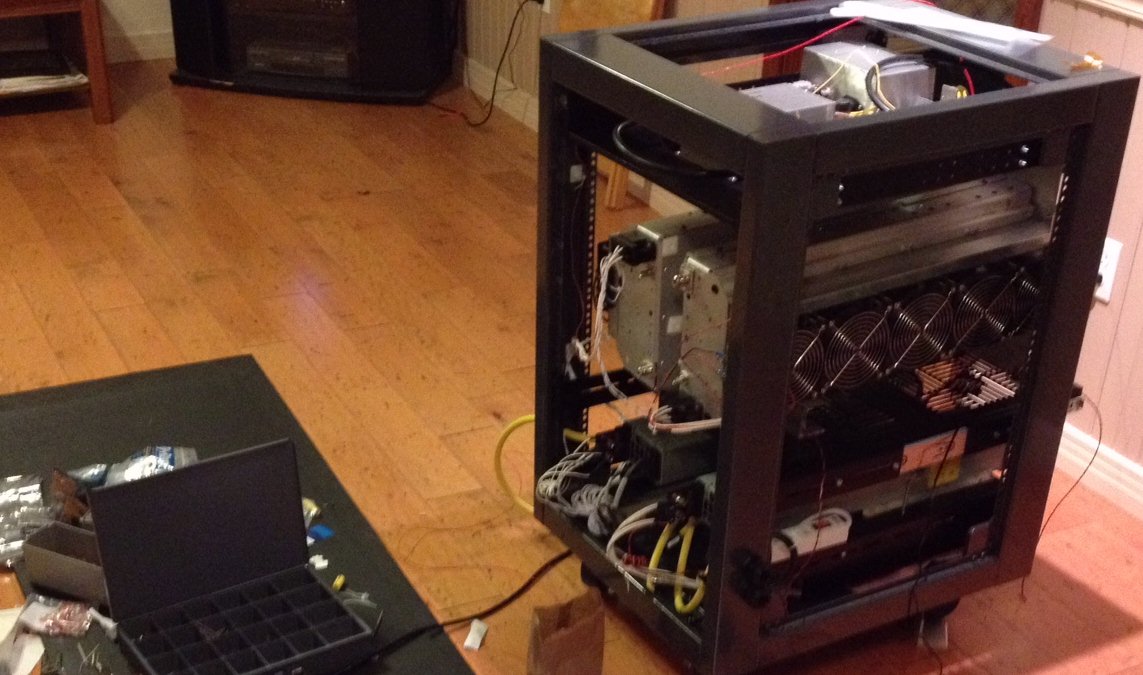
These
photos show how two of the amps were mounted
above the drawer of an old surplus computer
rack, by placing them back to back, on their
sides. When both amps were connected to the
combiner and filter, one of the amps
triggered a shutdown due to high SWR. As
explained in the "Cheese Bits"
articles, this is not unusual, and I had to
slightly advance the small SWR potentiometer
(next to the RF Coupler board) inside that amp
about 1/8 turn clockwise to permit proper
operation. Both amps then seemed happy and
the overall unit put out over 2500w into a
dummy load.
In the photo to the right, the unit is shown above putting out 1500w of very linear power into the antenna. You can see that each of the HPS3KW power supplies (rated at 51.4 VDC and 57 A) are running at about 59% of their rated capacity for this amp to put out 1500w key down. At 2500w output into a dummy load, the power supplies are each delivering about 47 amps. 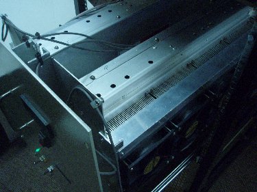 View looking down into the drawer when it is pulled out |
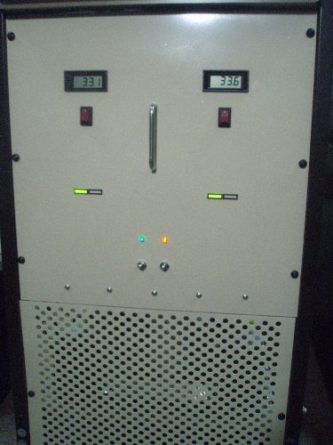 Front view of the finished amp, showing the current meters, and the red and green LED indicators that come mounted on the front panel of each amplifier. The toggle switch under the green panel lamp shows that 28 VDC is applied to the coaxial antenna relays. The toggle under the orange panel lamp is the standby/operate switch to activate the transmit relays, and only comes on when the 50 VDC is applied to the amps (and when the 28 VDC switch is turned on). The rocker switches below the digital meters select whether the meters indicate DC current to the amplifiers or relative power output. |
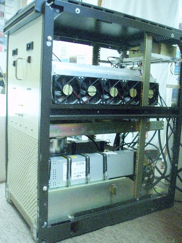 Side view of the rack with the perforated side covers removed, showing the cooling fans mounted on the amp heat sinks. The bottom of the rack holds the combiner cabling, and above that sit the two power supplies, with the dummy load in between them. The amps are mounted on standoffs above the drawer bottom, to allow air circulation up through the input holes in the sides of the amplifiers. As can be seen, ample room was left for good air circulation, as well as for all the cabling. |
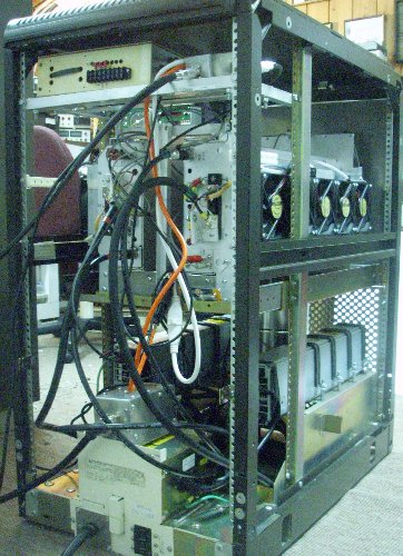 Rear view of the rack. The unit at the bottom contains the AC power relay, circuit breaker, and AC outlets. Above that is the 50 MHz low pass filter attached to the combiner cabling. Just under the top of the rack is a shelve that was added to hold the power splitter (on the right) for the input drive and the relay box (on the left). The relay box provides 28 VDC on receive and transmit to the various external coaxial relays, and also shorts the amplifier PTT lines to ground when it receives a ground signal from the station sequencer. That box also houses the 28 VDC and 12 VDC supplies required to operate its relays. |
Currently, no Channel 2 amplifiers are left. However, there are currently some Channel 3 amplifiers available, which work quite well on 50 MHz (see SECTION 1 above) and of course work very well also on 70 MHz. I also have some driver units available, which put out over 500w with under 1/2W drive; my MFJ-259B actually drove them to over 2w output! The driver units would make a great beacon transmitter for 50 or 70 MHz with 100 mW drive. The Channel 3 amplifier or driver units are available F.O.B. Frenchtown Montana for $400 each or $350 each if you purchase two at the same time. While they last, I also can make the special Harris rear panel RF output cable and Power Plug connectors available for an extra $50 per unit.
Shipping/packaging is extra. You can arrange to pick up the units here in Frenchtown, Montana, USA or they can be packaged and shipped to you at your cost. Please include $100 for each unit to be professionally packaged and shipped via UPS Ground within the continental USA, along with a UPS street delivery address. They are professionally boxed up to prevent damage and are shipped insured via UPS. The boxed weight for a single amp usually weighs around 33 pounds the way I get them packaged.
Please contact me directly to arrange for overseas shipments; packing and overseas shipment for a single amplifier made by regular mail service (insured International Priority Mail) usually costs between $160 and $260 but varies depending on the destination.
International payments can be made by PayPal or bank funds transfer, which usually takes several days. If you choose to pay by bank transfer, please contact me, and I will provide you all the specific account and routing information required. North American payments must be made in $ USD by PayPal (to my email address as listed on QRZ.com), certified check, cash, Western Union wire or U.S. or Canadian Postal Money Order to:
Richard L. Collister, Jr.
P.O. Box 73
Frenchtown, MT 59834-0073
TEL: 406 626-5728
Orders are accepted when payment is received. In other words, shipments go out in the order payment is received. GL and DX on 50 MHz (or 70 MHz, if you are in Region 1)! MNI TNX and VY 73, Lance W7GJ
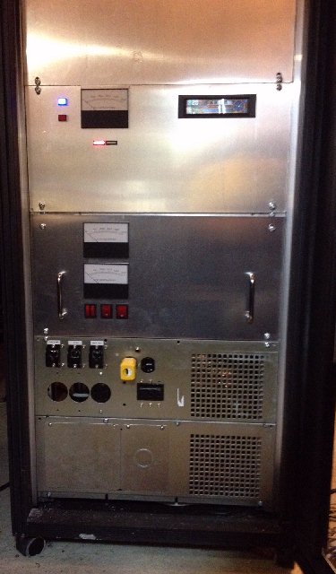
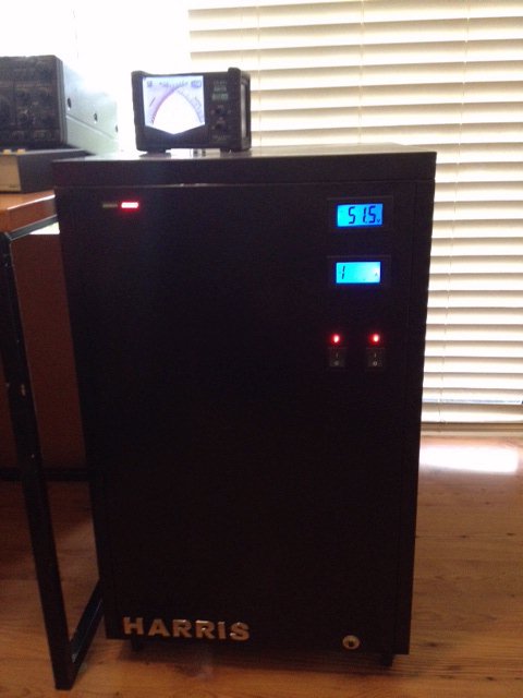
Space for two amplifiers in an old rack cabinet Single amplifier installed with power supply in a filing cabinet