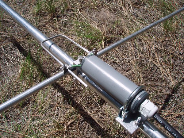
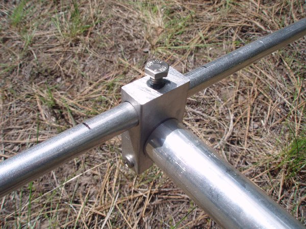
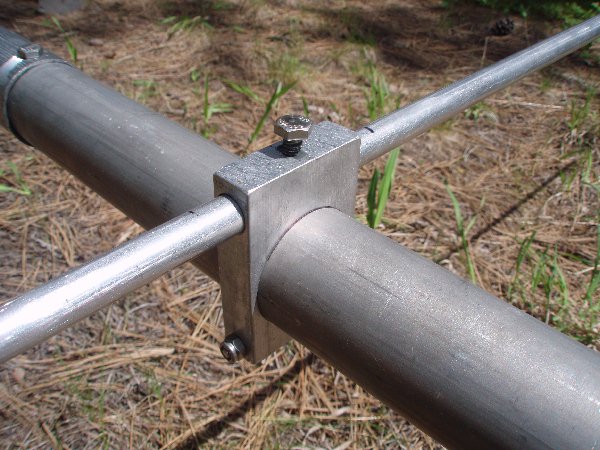
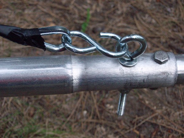
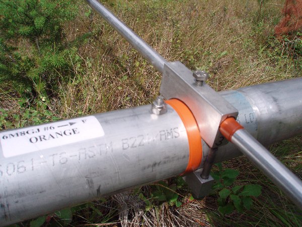
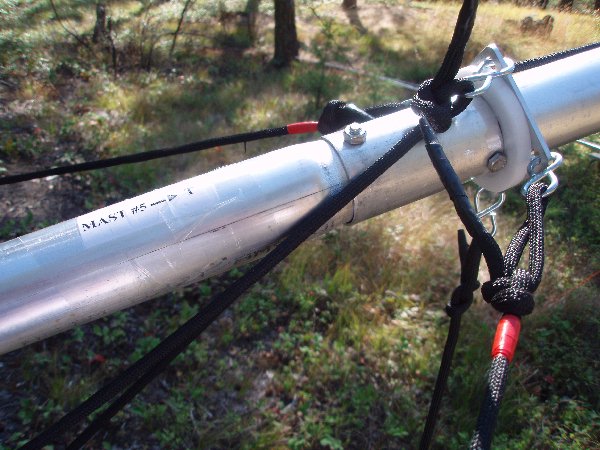
The photos below show the mechanical details of the 6MGJ. The elements are all 40" long middle sections of 1/2" OD tubing. The outer sections are 3/8" OD tubing secured at the proper extensions by the small element clamps shown. The elements are mounted to the booms using several different sizes of rugged clamps shown. Kevlar guy line is used to truss the boom, and it is attached to screw eye bolts that double in joining the boom sections together. I added S hooks to these screw eyes to permit easy and repeatable connection of the boom truss lines.
The driven element is a split dipole with a hairpin loop to transform the impedance to 50 ohms. It is then fed with 50 ohm coax through a ferrite choke with an N connector on it. The 6M8GJ instruction sheet calls for the Driven Element tips to extend out 36" each side of the center section. When I set up the antenna that way on the mast here (the boom was 21'-3" above the ground), the best match was just below 50.100 MHz. When the elements get wet (or if you stack antennas), the resonant frequency will go down even further, so you don't want to start out so low. I adjusted the Driven Element tips so they only extend out 35.75", and the SWR dip was around 50.215, which I think is perfect. That is how I will always set mine up in the future, so that is how I am marking mine to go together for assembly in the field.
NOTE: Be careful to follow the warnings listed in the W5WVO article concerning stainless steel fasteners when constructing the 6M8GJ yagi. Also be sure to check out the more recent notes at the end of this document!

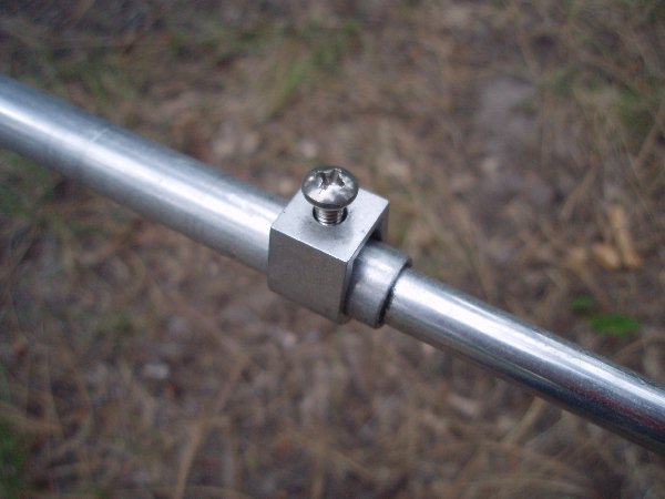
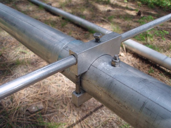
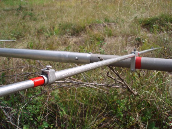
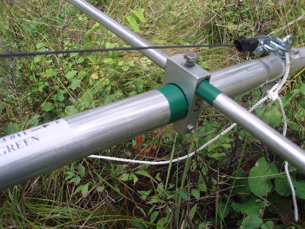
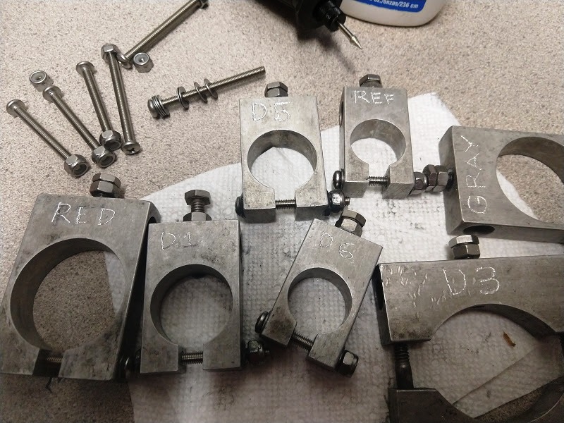
These photos above and to the right show how the boom parts and elements were marked for assembly using colored tape and printed labels covered with clear protective packing tape. Colored plastic tape (obtained at the local ACE Hardware store, or Radio Shack) was wrapped around the 3/8" tubing as "stops" next to the to 1/2" tubing so they can be quickly inserted to the proper depth and secured in the field. At least with my 6M8GJ, the correct overall element lengths corresponded to the 3/8" tubing being inserted 3" into the 1/2" center sections, except for the driven element pieces, which were each inserted 3.25". In addition, each element mounting block was labelled with a Sharpie to indicate the position on the boom. Correspondingly colored tape was then wrapped around the boom next to the rear end of each element mounting block, to mark its location.
When the antenna needed to be cleaned after the TX5K DXpedition, as much of the salt as possible was scrubbed off the elements and boom sections with an industrial grade "scratchy pad" under running water. The inside of the larger 1/2" tubing ends was scrubbed with test tube cleaning brushes that were 3/4" in diameter size. That size round bottle brush made a nice snug fit for cleaning the inside of those sections, into which the 3/8" diameter elements would have to cleanly fit with good electrical connections. When the elements are assembled in the field, it is important to coat the ends of the 3/8" diameter elements with anti-corrosion compound where they are inserted into the 1/2" diameter center element sections.
MANUAL ELEVATION MOUNT
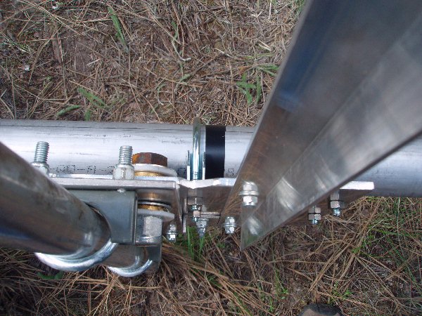
The actual elevation mount itself was constructed of two 1/4" aluminum plates. The plate attaching to the mast was 14" high x 4.375" wide. The pivot bolt was centered 1" in from the front edge, and 2.75" down from the top of the plate. A 1/8" thick sheet of HDPE 4.375" wide was secured by the lower U bolt assembly and the pivot bolt assembly.
The plate for holding the vertical extension mast and the boom itself was made from a plate 9" high and 15" wide. The pivot bolt was located 1.5" down from the top of the plate, and 6.75" in from the front edge of the plate. The pivot bolt itself was a 2.5" long, .75" diameter hardened steel bolt with a nylon locking nut. As you can see from the photos, the bolt runs through a bronze bushing mounted in each plate. Each bushing has a length of 5/16", so they join in the center of the 1/8" thick sheet of HDPE sandwiched between the two plates. An adjustable pressure plate with a 1/8" thick piece of HDPE underneath it provides a smooth surface to let the boom plate rotate under it, while still holding it tight against the 1/8" HDPE sheet. This aluminum plate is curved to match the radius of the pivot.
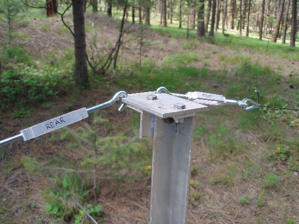
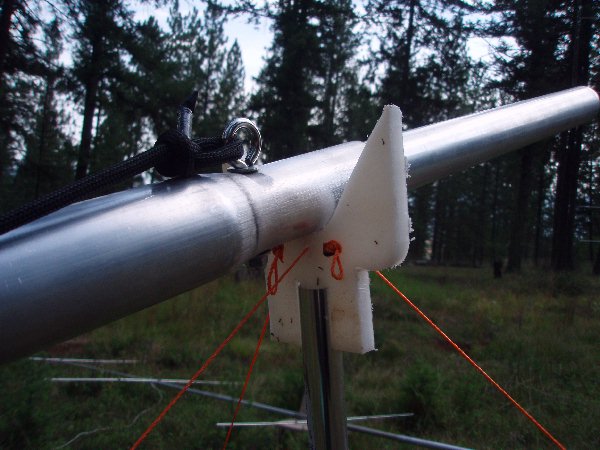
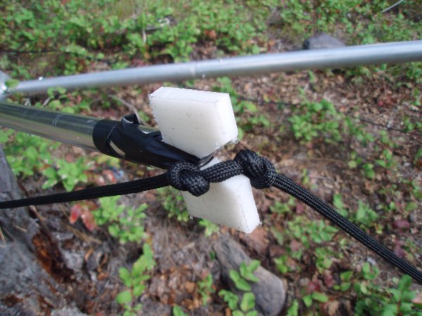
Mast extension with top extension plate so that the truss lines line up over the center line of the antenna boom so they will keep the boom straight, rather than pull it into a sideways bowed configuration.
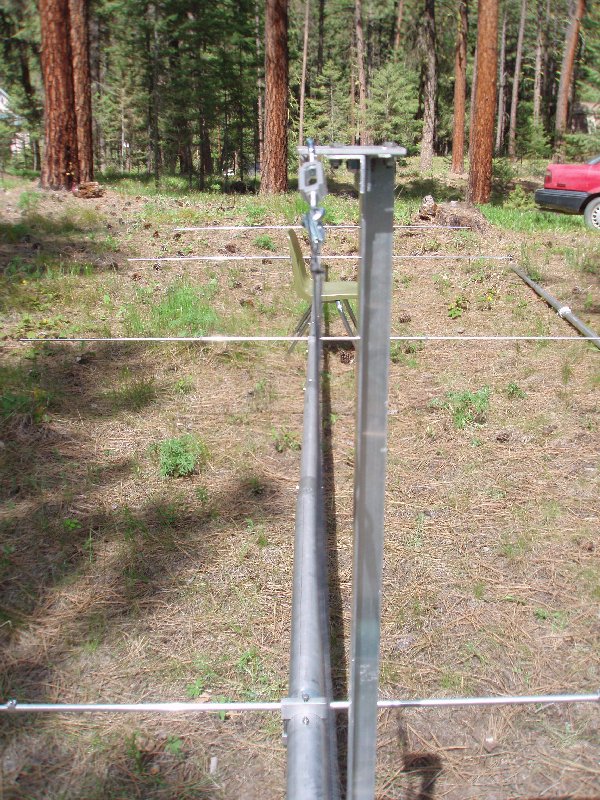
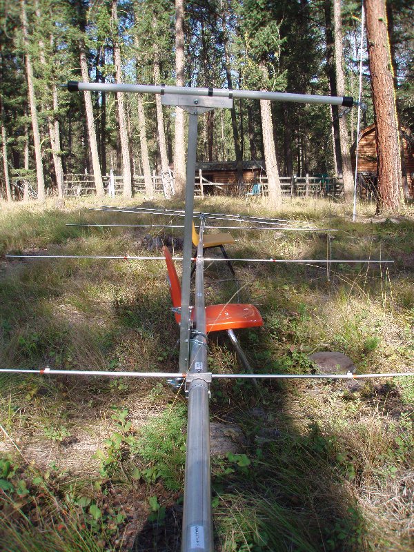
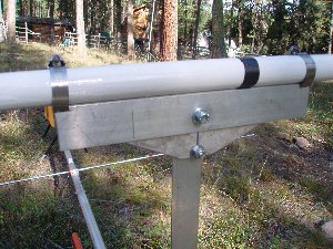
Overall view of the elevation mount. Note that in actual installation on the actual mast, the top of the mast must be flush with the top of the elevation mount in order to antenna elevation.
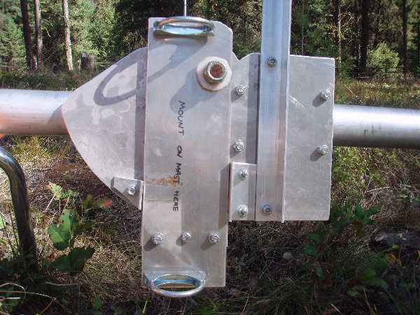
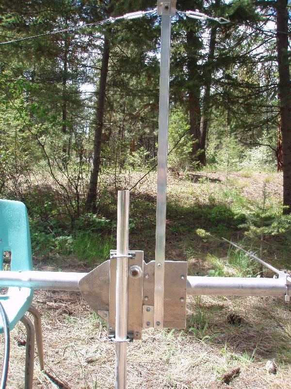
Mast side of the elevation mount. The boom is mounted so the antenna is slightly front heavy with the coax connected and taped to the boom; the angle aluminum stop between the mast extension and the mast plate prevents the antenna from going down below zero degrees elevation.
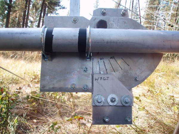
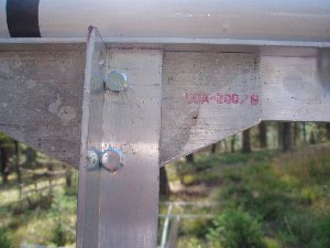
Boom side of the elevation mount. The top rear corner of the boom plate was cut away to reduce unnecessary weight, and the lower rear corner was rounded to permit smooth constant area under the pressure plate.
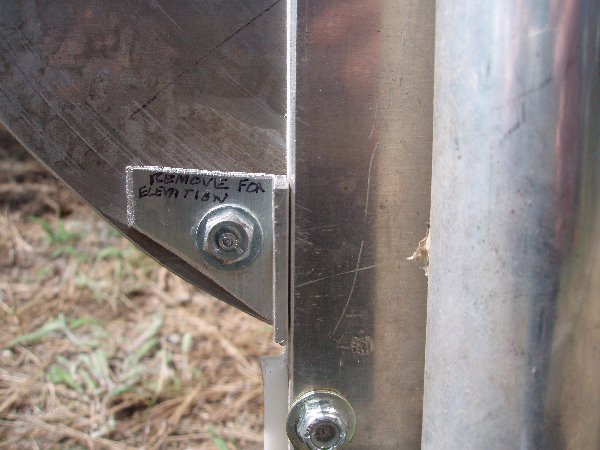
Closeup of the stop that is removed to permit elevation of the antenna. At the bottom of the photo is one of the bolts that holds the bearing plate assembly together.
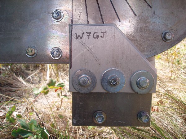
Closeup of the pressure bearing plate, showing the contour to permit the boom to come down next to it. The pressure plate and the 1/8" HDPE bearing pad are spaced out 1/4" by a pair of contoured 1/8" HDPE spacers, to match the thickness of the boom plate.
Top view of the elevation mount. With my mount and LMR-600 UF coax, I mounted the boom so that the front plate of the mount (right side in above photo) was 13.5" from the center of D3.
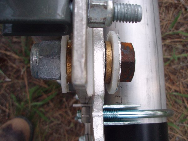
Top view of the pivot bolt assembly showing the bronze bushings that are tightly set into the aluminum plates, and mounted with 1" lock washers so they are affixed to the plates. The pivoting movement is between the bushings and the 3/4" x 2.5" hardened bolt that runs through them..
DOUBLE TRUSS MODIFICATION
I have changed the single boom bracing on my 6M8GJ to that of a double bracing, which affords an additional amount of side bracing. I found that using a pair of lines to the front and rear holds the boom very straight as well as from sagging....and there is much less tension in any of the lines than when only a single line was used.
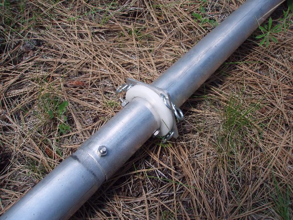
I started with a 40" long piece of 1-1/8" diameter fiberglass pole (a remnant from the local University pole vaulting department of the Track and Field). I purchased a couple of rubber feet to fit over a walking cane at the hardware store. I mounted a screw eye in the end of each of the rubber feet with some large washers and a self locking nut on the inside. Then I stuck one on each end of the fiberglass pole. When the guy lines are supporting the boom, the force will push the screw eys and rubber stoppers more tightly onto the fiberglass pole, so additional fastening is not required.
The fiberglass pole rests on a piece of angle aluminum, which has kerfs cut on the ends so that a stainless steel hose clamp can slide into the slot. The fiberglass pole is positioned so that the center of the pole is directly above the center of the antenna boom. It is held in place by the hose clamps.

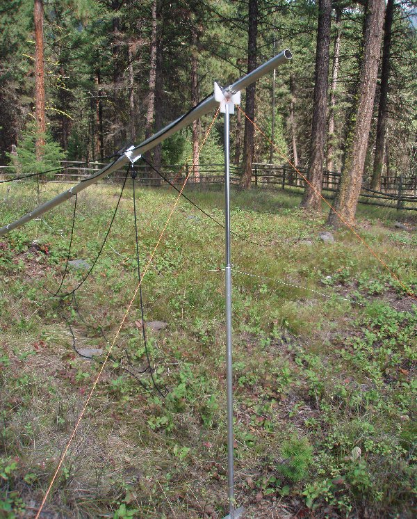
MAST GUYING AND AND ANTENNA RAISING
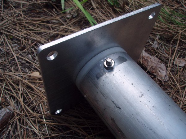
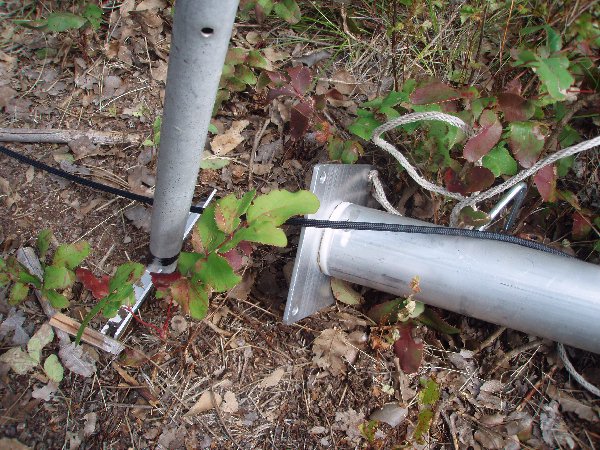
The photo to the left shows the base plate of the mast that is pinned to the ground with small stakes; the white piece is a plastic bearing sleeve that allows the mast to be rotated even though the base plate is secured to the ground. The photo below shows the upper bearing that permits the mast to rotate freely while it is held upright by the four guy lines. I added the S hooks shown to quickly attach the Dacron guy lines.
The following installation instructions assume you are using an elevation mount such as those that I built, with the integral extension mast to hold the boom trusses). In such a case, you can cut off the 1.5" diameter top section of the mast so only 14.5" sticks out above the last joint. This will make it easier to slide the elevation mount onto the mast, and will allow the antenna to be elevated freely.
NOTE: If only the standard boom to mast plate is used, the full length top mast section and the boom trusses will need to be installed on the antenna before bolting that final section onto the Portable Mast.
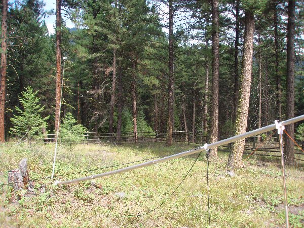
I worried for some time about raising the antenna on the mast, because if you raise it using the guy ropes (which are on a slip ring mount), the mast and antenna can turn as you raise it. The first thing I did was change one of the bolts that joins the top section of the Portable Mast to an "eye bolt" so I could tie a long 40' rope onto it for raising and lowering the mast without having the mast rotate (please see photo to the lower right). Raising it with this dedicated longer raising rope also provides more leverage than is possible from the lower point where the guy ring is located and it keeps the mast and antenna from rotating as it is raised and lowered.
With the Portable Mast assembled and laying on the ground, the first step is to attach the raising line as described above, and attach all four guy ropes to the guy ring. On the M2 Portable Mast I have, the distance from the base to the guy ring is 17'-4", and the point where the guy lines would intersect the center of the mast is 1.5" higher, or 17' 5-1/2". From simple geometry, it can be seen that, in order for the mast to be securely raised and lowered, the side guy lines must form a triangle of the same dimensions when the mast is lowered or when it is upright. For this to happen, the distance from the guy line stakes to the centerline of the mast also must be 17' 5-1/2". From the Pythagorean Theorem, this means that the length of the guy lines from the stakes to the point where they would intersect the center of the mast (if they did extend up past the guy ring) must be 24' 8.5", or 24' 5-1/4" long from the guy ring to the stake. After the guy lines were tied at the guy ring S hook and stake, the lines as supplied with my Portable Mast were about 6" too short to meet the above requirements.
I therefore replaced the two side guys with lines that were 1' longer so the guy lines could be properly sized to permit the side guy stakes could be properly located out 17' 5-1/2" to the sides from the center of the mast base amd keep the mast properly held centered as it is raised or lowered. I marked both ends of these slightly longer side guys with colored tape to identify them. The bottom/back guy is less critical, and was staked right next to the mast and 16' up from the bottom plate. Similarly, the top guy length is less critical and will be staked at an appropriate place to hold the the mast vertical. If your soil is very loose gravel or sand, the standard anchor stakes provided with the mast may not be secure enough. You may need to use other stronger anchors such as steel rebar driven into the ground.
The next step is to anchor the base of the mast. Run a short rope with knots (to prevent slippage) through the two bottom holes in the bottom plate and secure it to keep the bottom plate from moving toward you as you pull on the raising rope. In the photo to the left, a screw anchor is used for this purpose to hold the base of the mast securely to the ground. The screw anchors are inexpensive and sold in hardware stores as anchors for dog runs or chains. This method will allow the mast to hinge up, but will prevent it from leaving the ground (which can happen when the antenna is mounted on the end and there is a fulcrum under the mast to support it and keep the antenna off the ground).
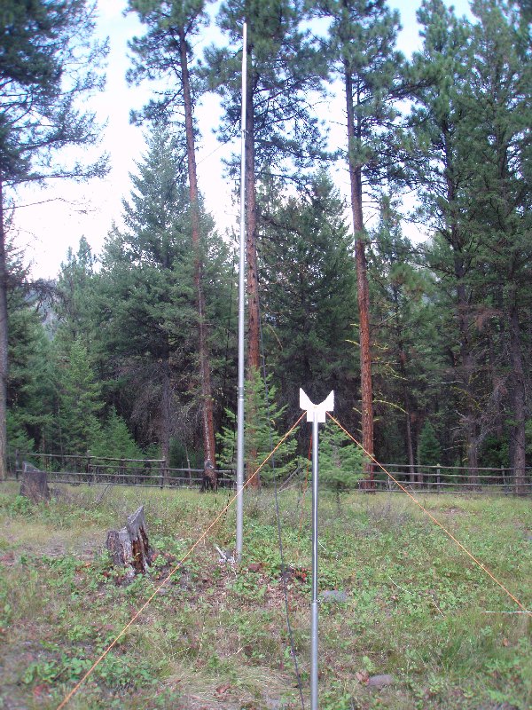
Next, find something to support the mast between the guy ring and the top end of the mast. The lower end of the top mast section needs to be held about 6' off the ground in order for the antenna to be installed. You can use a vehicle roof, tall garbage cans, a small step ladder, the shoulder of a large helper, etc. wedged under the mast. In order to have the flexibility to raise the antenna without any of those things, I built a lightweight telescoping 6' post that can be guyed with tent pegs and nylon string to support the upper end of the mast. A simple cradle was cut from some HDPE and inserted into the end of the post to support the mast. A simple bottom bar was made of angle aluminum to keep the post from sinking into the ground.
With the Portable Mast secured as described above, it is easy for one person to pull on the raising rope and bring the mast up in the air. Do this a few times, making sure that all the guy rope stakes are in the correct position so they are tight and the mast is vertical when it comes up all the way. Then you can lower it down to the support post again. When everything seems to be properly staked, you are almost ready to raise it with the antenna.
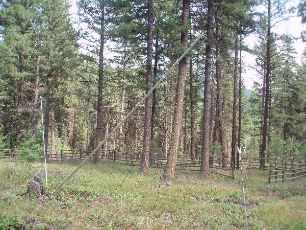
In order to obtain enough leverage to raise the mast when the antenna is mounted out on the end of it, a 10.5' high "falling derrick" was constructed. Knots were added in the raising rope (see photo to the right) to allow the top end of the falling derrick to pivot as the rope is pulled. The bottom end of the derrick was placed on a piece of aluminum to spread out the pressure on the ground, and permit it to easily pivot without digging into the ground. The base of the derrick is placed just behind the base of the mast, and held in place by tension on the raising rope. It is a good idea to practice raising and lowering the mast a few times with this derrick even though it is not really necessary until the antenna is mounted on it.
The coax should already be installed and taped to the boom of the assembled 6M8GJ. In addition you should already have two 1/8" nylon lines tied to the rear boom section and one 1/8" nylon line tied around the boom and through the eye bolt (used for the front boom truss line) at the front boom section. If you want to have an elevation indicator, you should have something like a plastic protractor with a hinged stiff wire attached to the boom near the reflector; however, labeling the elevation mount as shown in the photos can provide a much more durable solution.
Pick up the antenna, rotate it 90 degrees, and place it on the elevated end of the mast. The 6M8GJ boom should lay on the UPPER SIDE of the mounting plate, to provide additional ground clearance so the element tips do not dig into the ground. Remember to tape the coax to the mast and allow a large loop for it to go around the guy line slip ring.
Then run around to the other end of the mast, inset the raising line into the notch at the top of the falling derrick and start pulling it up. If you have helpers, they can walk toward the base of the mast and helps to push it up as you pull.. While you hold the mast vertical with the raising rope, the helper can then stake in the fourth guy line. The antenna is then ready for use.
Lowering the antenna is done the same way, except in reverse. Remove just the. fourth guy line stake and lower the raising rope while your helper walks out toward the antenna, helping to receive the weight of the mast as it is lowered onto the temporary support post. If you use the falling derrick in reverse to lower the mast, there won't be such a sudden increase in weight as the lowered antenna and mast approaches the support post. If you have a helper, using the derrick will make it much easier for them to share the weight of the mast and antenna as it is lowered. Here is a Windows movie showing lowering the antenna during the 6m EME DXpedition to 3D2. Here is a movie showing the solo antenna raising at T8GJ in 2016.
With the top of the mast safely on the support 6 feet off the ground, you can free the coax from the mast, unbolt the 6M8GJ, and slide it off the top of the mast, rotate it 90 degrees and set it on the ground or across some folding chairs (or other supports). I hope this helps you successfully get your 6M8GJ working successfully and quickly out in the field! It is well worth the time to set it up and mark everything at home before you go! GL and VY 73, Lance


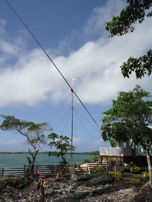
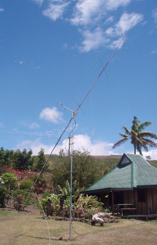
6M8GJ in use at 5W0GJ in August, 2011
Prep work before the deployment:
It is IMPERATIVE to assemble the antenna before you go to the field. My first assembly of the antenna took about 8 hours. The goal was to learn how it goes together, organize the parts for a quick deployment and learn what tools and techniques are required.
I learned that to minimize build time the basic location of elements and parts should be marked on the beam, the parts required to be mounted on the boom pieces should be placed into individual Ziploc bags. These markings I left on the cleaned up parts.
The truss attachment at the mast was ambiguous in concept and parts. We used a basic hose clamp to secure the truss. The balun mounting plate was missing. In the field we used black tape to secure the balun.
In the field:
The antenna went quickly together. Perhaps Dave and I spent two hours for assembly. We spent about the same time to raise, guy and orient the antenna. This involved some vegetation management.
The antenna was mounted on a SpiderPole Al Mast.
NoAlox grease was used on all major components.
The antenna was assembled over a tarp. The base material was broken up coral and if a part was dropped the probability of finding it was low.
The SWR was good and the resonant frequency was close enough so we did not have to make any mechanical adjustments.
Our operating location was about 250 ft from antenna. We extended the 100 ft supplied LMR400 coax with new RG8 to complete the run.
I recognized the criticality of the antenna shipping box so I secured it in my tent to keep it out of the rain.
The antenna take down was rushed because of an impending storm. The antenna was not cleaned with fresh water. So salt residue was left on the parts.
Post trip cleanup:
The antenna was in a salt water environment for approximately 4 months.
In the trip home the box was exposed to water and was pretty much destroyed. I found corrosion on all parts which required cleaning. I kept the markings on the antenna pretty much intact. The 8-32 screws in the element to boom mounting saddles were locked by corrosion. In the process of "freeing" I destroyed one saddle. NoAlox was not applied at these joints.
M2 was responsive to my request for parts. However, they would not ship me an empty box to repack the antenna. By chance the identical box arrived in another shipment to me. I used it with the old corner protectors for shipment to the next user.
A problem I had was stripping out the 8-32 screw in the last director or reflector element mounting clamp. Sure I had spares but trying to get it out of the clamp added about an hour to setup on the CP6GJ DXpedition, and basically meant I had to wait until the next morning's light to finish aligning the elements and raise the antenna. OK, so I was beat from being up all night traveling and spending all day putting up the mast and assembling the yagi, and I really needed to rest instead of getting on the moon anyway...
But this also happened to me once
before at V6M and I heard it also happened to
KB7Q with my 6M5XHG in PJ2. At V6M, it was no big deal
- the stripped screw was just pulled out and replaced
with a spare. But in CP, it cost me valuable assembly
time and I needed to borrow some extra tools from the
hotel manager because the stripped connector could not
be tightened sufficiently OR removed from the aluminum
clamp :-( I wish I had had a hack saw to just saw
through the screw, but there was none available in the
hotel tool box, and I haven't been carrying a hack saw
blade with me on trips. Might be something to think
about in the future, though ...
One thing I had already done was to add stainless steel washers on both sides of all the clamps (screw and nut side) and coat them all with NAOLOX. That helps prevent them from binding on the aluminum clamp itself. However, it does not solve the problem of over-tightening the screw to try to get the clamp tight enough around the small boom ends to keep the element from moving in high winds. Especially with the smallest diameter boom sizes, it is really tough to get the clamps tight enough without stripping the 8-32 hardware.
Therefore, I finally decided to drill
out all the screw holes in the mounting blocks with a
13/64" drill bit and replace the S/S 8-32 hardware on
all the mounting clamps with S/S 10-32 screws, washers
and Nylok nuts. Drilling out the holes so the 10-32
size screws loosely fit through was definitely worth
doing to help prevent binding. I did it to this 6M8GJ
and my 6M5XHG so I don't ever have to worry about
stripping out the screws and/or nuts ever again ;-)
And at the same time, I engraved all the element mounting blocks with the element description on one side and the color coding of the elements on the other side. This solved the problem of the sharpie markings wearing off each time!
Since this original article was
written, I built a new elevation mount that is less weight,
easier to build, and supports the antenna directly
over the center of the mast: