This 98.8' (30 m) long portable antenna
was produced by VE7BQH in response to the growing interest in 6m
EME.
Especially with the increasing popularity of JT44, coupled with the
availability
of commercial 6m amplifiers capable of 500-1500w output, 6m EME is
becoming
within the grasp of many stations around the world, and is responsible
for a number of DX stations getting close to 6m WAS! In many
cases,
all that is required for home or DXpedition stations, is to have JT44
mode
capability, a good antenna and several hundred watts or more.
Many
home stations may also be interested in this antenna project, now that
the propagation of this solar cycle is declining (or long gone, for
some
of us!), and a larger antenna than was required for F2 or TE
propagation
will now be warranted to provide propagation via EME.
However, please NOTE that this
type of antenna works best closer to the equator (below 30 degrees ).
This is because in those regions, the path of the moon is
frequently
mostly up and down. At higher latitudes, the movement of the moon
is
largely in azimuth, and this type of fixed-azimuth antenna is not well
suited
to such a situation.
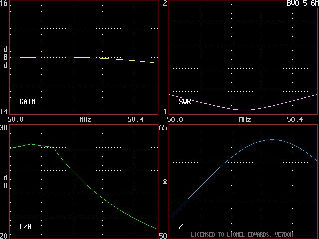
This 15 dBd (free space gain) antenna was designed by DJ9BV and is from the BVO series. VE7BQH scaled it to 6 Meters in YO 7.5. Applying this design to a rope yagi construction technique achieves the following objectives:
1. Portable - it can be rolled up for
transport.
2. Relatively inexpensive to construct
3. High gain antenna should be capable of 6m
EME
4. Sloper configuratin by hanging from one end
broadens useful vertical pattern and permits more moon time.
5. Raising main lobe in elevation reduces adverse
interference from tropo ducting, F2 "entrapment" and/or auroral
interference.
6. The high main lobe also prevents blockage by local obstructions
(tall
buildings, mountains, etc.).
As discussed on my web page for the 6M35WL, I consider that 70' yagi (with 14 dBd free space gain) to be about the minimum free space gain for making 6m EME contacts (with other similarly equipped stations, without ground gain). With my 6M35WL and 1500w, I am able to copy my own CW echoes some of the time while elevated, and I therefore found it was possible for me to contact similarly-equipped stations. Note that a 6M7JHV yagi typically has the same amount of forward gain when it is on the horizon and develops ground gain lobes, and I was therefore able to complete contacts with 6M7JHV stations while they were aimed at the horizon (and I was elevated). (Of course, now with my large 4 x 6M9KHW yagi EME array, contacts are now much easier, but 6m EME contacts with single yagi stations is STILL quite a challenge!)
What is shown below is a rope yagi design that will meet or exceed this "threshold' 14 dBd gain over a relatively broad (20 degree) vertical beamwidth, thereby providing time for the moon to move between the first two ground gain lobes at a distant single yagi station aimed at the horizon. And, during the peak when the moon is at 20 degrees elevation, there is even an additional 2 dB gain, resulting in equivalent gain to a pair of 6M9KHW yagis pointed skyward..
This design uses .375" (9.5 mm) diameter thin wall aluminum elements, which are to be supported on two parallel non-conducting lines that will not stretch, such as dacron, Phyllistran or polypropylene (will not work if the antenna is to be left out in the sun for an extended period of time); the lengths shown for the antenna elements will only be correct if .375" diameter aluminum tubing is used for the elements. The antenna is meant to be suspended on one end, to slope upward at a 20 degree angle. If desired/necessary; sag can be reduced by hanging a third line above the antenna and extending several vertical support lines (such as in the middle and between the middle and ends) down from it to help hold the antenna up.
As can be seen below, the peak gain is at an
elevation
of 20 degrees, and the forward gain is mostly equal to or greater than
14 dBd over a 20 degree range of elevation between 8 and 28
degrees.
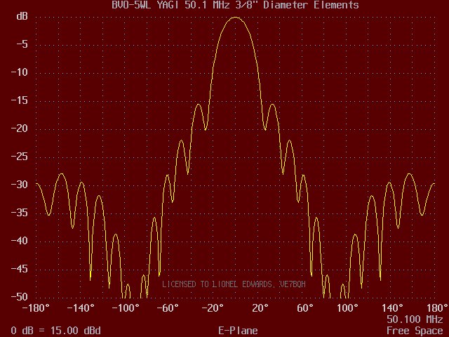
As can be seen from the free space pattern below, the rope yagi also has gain of at least 14 dBd over a beamwidth of 20 degrees azimuth.
The intended use of this antenna is to provide gain in a specific direction, such as toward a particular azimuth where the moon is intended to rise or set. Since the moon changes declination every day, over the course of a month it is usually possible to find at least a couple common windows with another horizon-only station. Another advantage of this sloper rope yagi is that it can be steered somewhat (to adjust for the changing moon declination and corresponding change in azimuth of moonset or moonrise) by moving one end of the yagi (preferably the lower end). In an ideal situation, the transmission line to the Driven Element can be kept very short, with the yagi extending out away from the operating position.
A few notes about the configuration of the rope yagi follow. If the yagi is 99' long, and there is 10' of extra rope on the high end (to attach to a mast or tree), and 22' of extra rope on the lower end (to anchor the antenna to ground), the reflector will be 7.5' off the ground, resulting in the driven element being 10' above the ground (required for designed 50 ohm impedance) when the yagi is supported at a 20 degree angle. The overall length of the entire assembly as described here, is 131', which requires a single support point 45' high. The amount of space required on the ground for this antenna is 123'. For more specific details on construction of such antennas, please refer to the the following links:
43
Element 144 MHz Rope Yagi by VE7BQH
70'
Long 50 MHz Rope Yagi by AA7A
|
|
|
|
| Reflector | 115.5756 | 0 |
| Driven Element | * | 43.5966 |
| Dir 1 | 109.0938 | 60.5823 |
| Dir 2 | 107.4832 | 102.4803 |
| Dir 3 | 104.6772 | 152.3049 |
| Dir 4 | 104.4608 | 209.1503 |
| Dir 5 | 104.1362 | 280.8299 |
| Dir 6 | 102.3998 | 354.4345 |
| Dir 7 | 101.8558 | 426.9067 |
| Dir 8 | 101.8558 | 503.9085 |
| Dir 9 | 102.1824 | 587.7045 |
| Dir 10 | 101.2026 | 674.5579 |
| Dir 11 | 100.7666 | 766.6204 |
| Dir 12 | 100.7666 | 858.9092 |
| Dir 13 | 100.4398 | 944.7435 |
| Dir 14 | 101.4204 | 1027.2938 |
| Dir 15 | 100.5484 | 1109.7311 |
| Dir 16 | 99.4568 | 1183.9019 |
*The antenna is designed to provide an impedance at the driven element of 50 ohms, provided the driven element is 10' (3 m) above the ground (reflector is 7.5', or 2.3 m above the ground). This facilitates the following approaches for driven element construction:
1. 4:1 folded dipole with balun
2. T Match with balun
3. Direct coax feed to a split
dipole with (preferred) or without ferrites to
provide a line
isolator/current
balun.
Specific dimensions will
depend
on the actual type of construction type selected for the Driven Element.
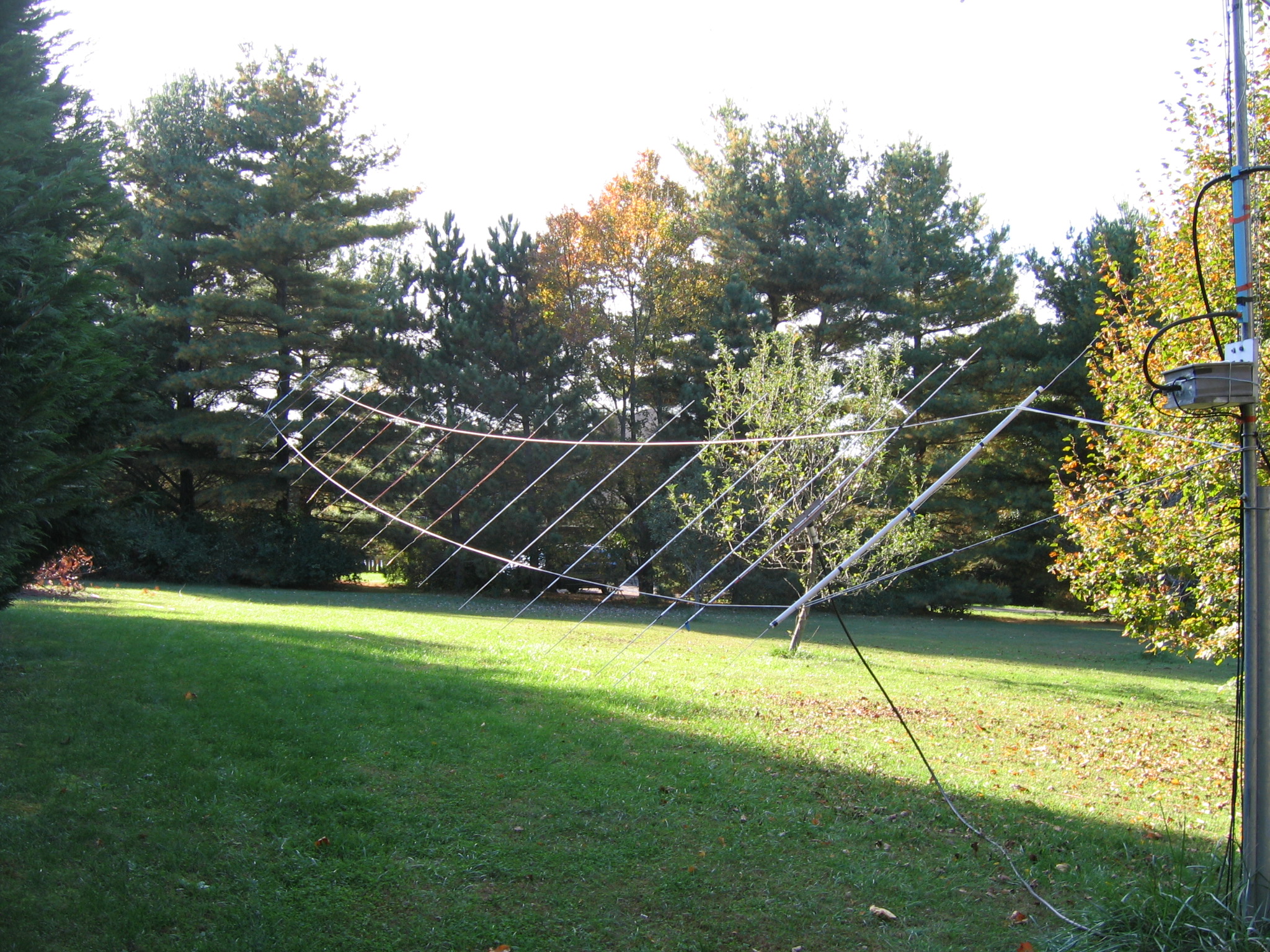
Below is the 6m rope yagi in the backyard at KD3UY:
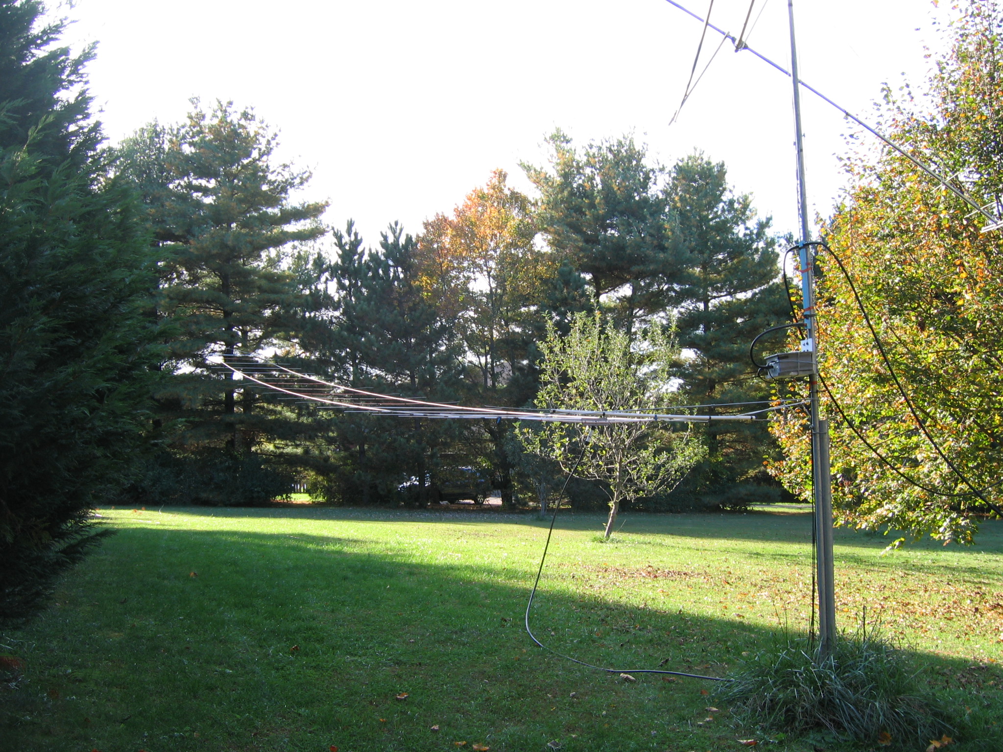
And here is a view with it rotated to better show the construction...
This page most recently revised 18 October, 2008