I am grateful to ND0B, who provided information on how the circuit
board of the this ARR preamp was laid out, making it very easy to
break into the preamp output line, and provide the option of
breaking out the preamp output to route it to an external
receiver. In my case, I wanted the option of connecting the
preamp to a USB RTL Dongle on my laptop computer when operating
portable.
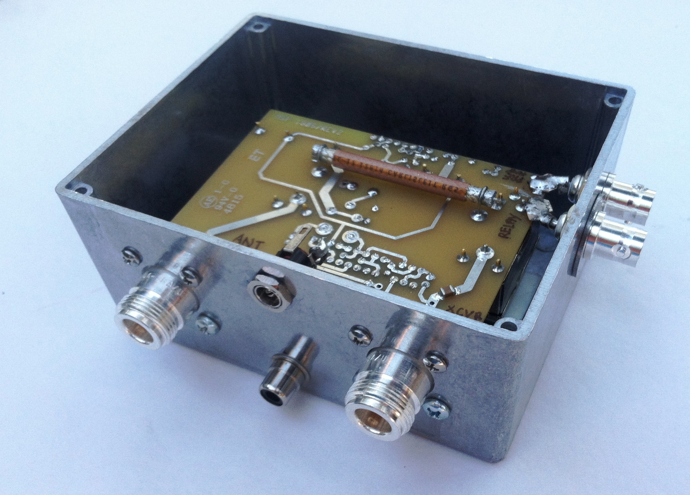
As can be seen in the photo below, the standard ARR preamplifier was
simply mounted in a new die cast aluminum enclosure, adding a power
recepticle for the 12 VDC input, along with an RCA connector for
manually putting the preamp into transmit (bypass) mode. The
photo was taken before I installed an LED pilot lamp next to the 12
VDC connector, to indicate that the unit had power.
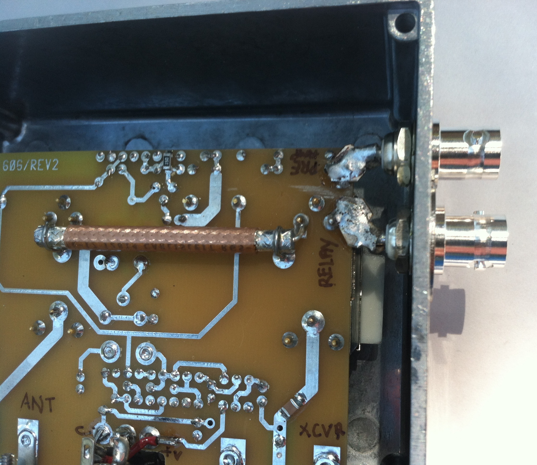
The photo below illustrates where the circuit board trace was
broken. Each side of the circuit was connected to newly added
BNC connectors.using silver plated straps. A short BNC
jumper connected to those terminals restores the original unit
operation of providing preamplifier output to the
transceiver. However, the preamp output can also be
connected to a low loss splitter so the transceiver and a separate
receiver can share the preamp, or the preamp output simply just can
be routed directly to the separate receiver.
(August 8, 2017)
