VE7BQH
BQH9-6c 50 MHZ YAGI
DESIGN
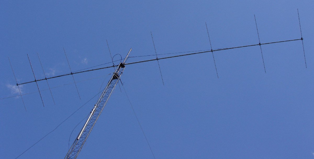
The "BQH9-6c"
Antenna - A 9 Element Yagi for 50.150 MHz with 12.2 dBd gain, and
a 50 ohm direct feed (thanks to W1IPL for finished antenna photos)
This antenna was designed to be an easily-constructed, very strong and
durable antenna, with over 12 dB gain (compared to a dipole), and
capable of being used effectively for EME contacts when aimed at the
horizon. With the use of weak signal digital modes, this antenna
should be able to produce contacts with larger stations, even while
elevated off the horizon. A pair of these antennas, or an array
of four such antennas, would make an excellent steerable 6m EME array.
NOTE: The details
of this design must be followed strictly to obtain the anticipated
performance. In other words, you MUST
use the same spacing and mounting of the insulated elements, the same
element diameters, the correct lengths shown, etc.
Many thanks to the efforts of VE7BQH for his fine contribution,
diagrams and notes, which are shown below.
The "BQH9-6C"
Construction Notes
1) BOOM
material
is assumed to be 2" diameter aluminum tubing, although slight
variations in diameter are not considered significant.You will need to
plot the element locations on paper versus the joints in the boom, to
make sure no elements end up on a transition joint.
It is normally a pretty easy thing to adjust the transition joint to
not
coincide with an element by either moving where the antenna starts on
the
boom or changing where the joint happens.
2) TRUSSING of
the boom at right angles to the elements can be done as required, with
turnbuckles and steel cable to keep boom sag minimal. Any lines
added to reduce side-to-side bending in the plane of the elements
should be done with non-conductive material such as Phyllistran, and
should be held out to the sides with non-conductive material such as
fiberglass tubing. Furthermore, any such lines should be
positioned so they do not bear down across the elements when encumbered
by ice or snow.
3) ELEMENT TO BOOM PLATESare
made
from
1/4" thick Lexan or HDPE insulated material. There
is no boom correction for the type of insulated element mounting used
here. That is, the boom correction is under a 1/64" and is beyond
any reasonable cutting tolerances. This assumes that you are using
small metal U bolts to fasten the elements to the lexan plates;
alternatively, you could connect the elements to the plates with a pair
of small diameter stainless steel screws and nylon locking nuts (such
as 10-32) on each side of the centerline of the plate. In eithe
case, this should introduce only a minimal disturbance (provided they
are only as long as required to hold the materials
together).
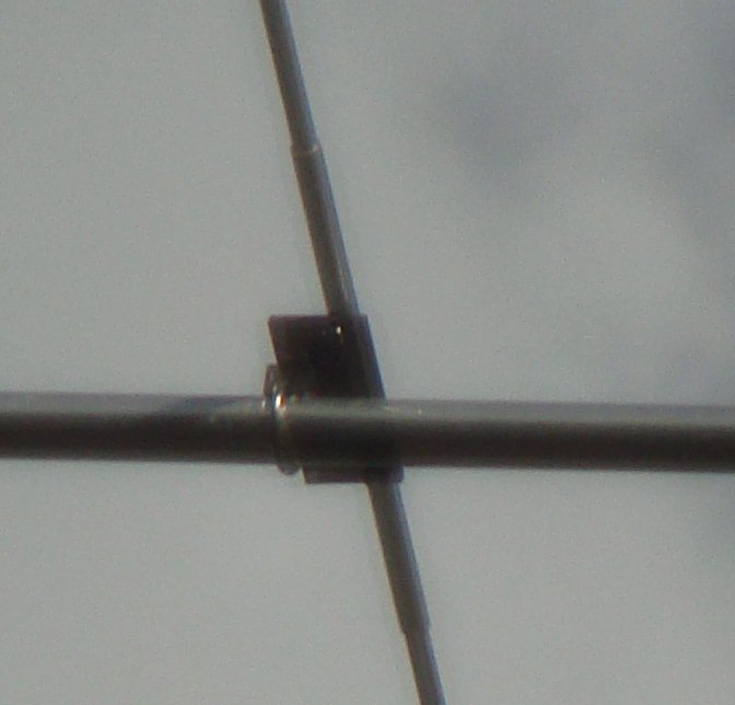
Each 1/4" thick lexan
(or HDPE) mounting plate is mounted to
the boom with a stainless steel "muffler" style clamp so the bottom of
each element
is 5/8" above the boom. This dimension IS critical. If your
particular mounting U bolt has a saddle that introduces a different
spacing, use a thicker piece of insulated plate so that the elements
are still separated from the boom by 5/8".
4) DRIVEN ELEMENT is
constructed using 1" diameter aluminum tubing, with some short sections
of 7/8" diameter tubing sticking out on each end, to allow for some
final VSWR adjustment. In addition, D1 may have to
moved slightly to adjust VSWR. It is difficult to capture every
capacitance in the program consequently the reason for some real world
touch up.
For mechanical stability, it is suggested that a 7/8" diameter piece
of teflon be inserted in the ends of the two driven element
halves, to provide good alignment and rigidity where they are attached
to the mounting plate.
5) CONNECTION OF
COAXIAL CABLE
to the split dipole must be kept as short as
possible. The inside ends of the split dipole should be no more than
1/2" apart to allow the coax connection to be kept short. VE7BQH
recommends you use crimp on spade lugs and also solder them with silver
bearing non lead solder (available in any large building supply
etc). If the antenna is going to be left installed for an
extended period of time, you can then seal all the connections with
non-taminating (non acetic acid curing) silicone.
6) FERRITE CORES
with the proper mix, such as the 1/2"
RFI CORE
(available from THE RADIO WORKS at http://www.radioworks.com), are used
to choke the RF currents in the outside of the coax. The number
of ferrites you will need is dependent on the power you will
use. 1 ferrite will handle up to 600 watts; 2 ferrites will handle 1200
watts, etc. The test is simple, the
ferrite should only be warm to the touch under sustained power. The
ferrites must be positioned as close to the feed
point as possible. As the ferrites are snap on, they need to be well
wrapped to ensure the two faces of the core are kept dry and firmly
together. Large size shrink tubing works well for this.
7) PARASITIC ELEMENTS
are constructed using center sections of 5/8" diameter tubing, with the
outer portions of each element being 1/2" diameter tubing.
8) ELEMENT LENGTHS
shown in the table below are the HALF
length.
Therefore, to obtain the overall lengths for the directors and
reflector, take the .625 length and the
.5" length, add them together and then multiply by TWO.
Example: Reflector = 12" +
46.4445" X 2 = 116.889". The
driven element is done the same way but uses the 1" and .875
diameters but will be kept in two halves.
There is no allowance shown for the extra material that will have to
be used when the smaller tubing is inserted into the larger
tubing. It is anticipated that each joint in the elements would
probably require several additional inches, and that the joints
would be secured with one or more short stainless steel screws with
nylon locking nuts.
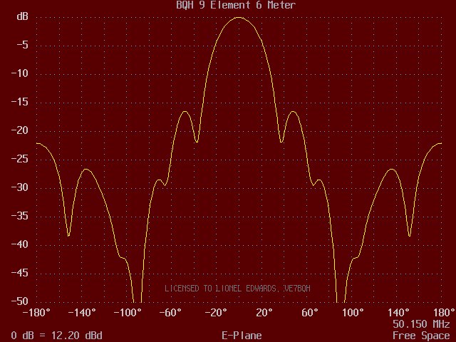
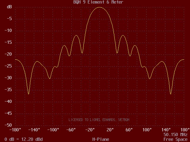
BQH 9
Element 6 Meter
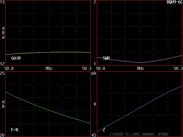
6063-T832
50.000 50.150
50.300 MHz
9
ELEMENTS,ALL DIMENSIONS SHOWN
ARE IN INCHES
SPACING
FROM
EXPOSED HALF LENGTHS OF EACH SIZE TUBING
REFLECTOR 0.6250 1.0000
0.8750 0.5000 DIAMETER OF
ALUMINUM TUBING IN INCHES
0.0000 12.0000
0.0000 0.0000 46.4445 REFLECTOR
40.0000
0.0000
50.0000 5.6407 0.0000 DRIVEN ELEMENT -
DIRECT 50 OHM FEED
62.0000 12.0000
0.0000 0.0000 42.9632 DIR 1
115.9397 12.0000 0.0000
0.0000 41.6255 DIR 2
201.3638 12.0000 0.0000
0.0000 40.5285 DIR 3
285.6098 12.0000 0.0000
0.0000 39.8537 DIR 4
385.4554 12.0000 0.0000
0.0000 39.8850 DIR 5
467.9373 12.0000 0.0000
0.0000 40.3807 DIR 6
536.0000 12.0000 0.0000
0.0000 39.0541 DIR 7
9) STACKING
BEAMS
is recommended as follows: E plane= 33.4', H plane = 30.63'
You could go down to 90% of these values with minimal gain loss.
Last updated May 22, 2010