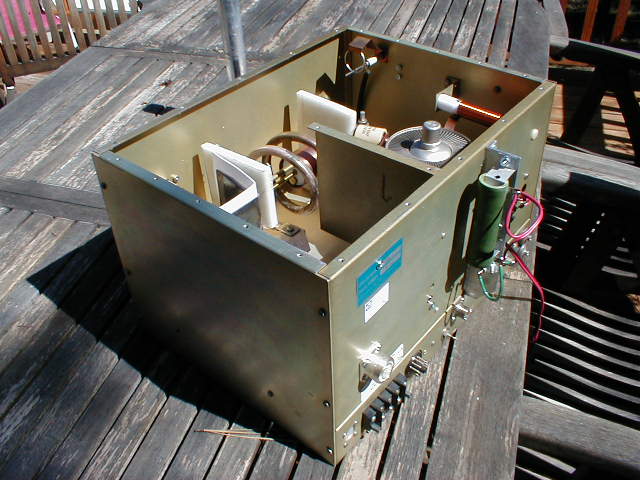
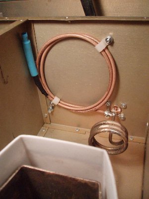
Rear view of the Henry 3000D converted to 6m. Note the 50k cutoff resistor and 12 VDC zener diode mounted on the back panel. You can also see the new 7/16 DIN RF connector installed in the rear of the Tank Compartment. No RF is run under the chassis in that half of the amplifier.
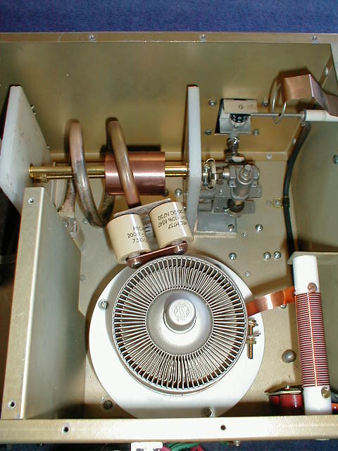
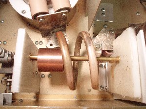
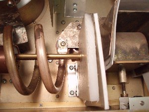
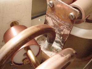
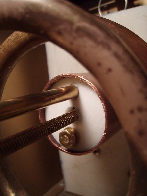
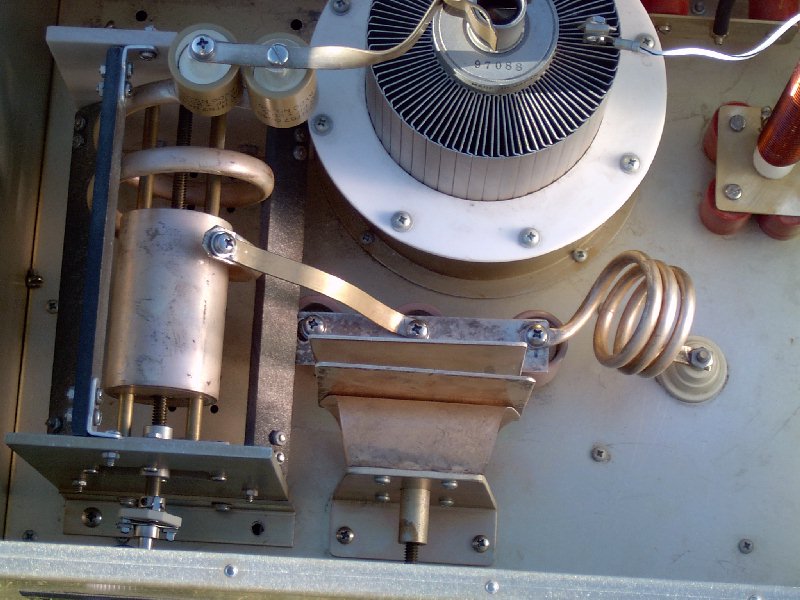
Top view of the tank compartment from the rear of the RF deck. The blocking capacitors used were a pair of 200 pF attached to a copper strap that is silver soldered to the anode clamp. The coil side of the connection is to a silver plated brass plate, with the coil silver soldered to it. A pair of 50 pF blocking capacitors were tried, but this circuit would not resonate because the slug could not be pulled far enough back out of the main tuning coil, and the loading capacitor needed more capacitance. Using a pair of 500 pF blocking capacitors required that the slug be inserted about halfway into the coil. Using a pair of 200 pF blocking capacitors seemed to work just as well, and only required the slug to be inserted about 1/4 of the way into the large tank coil.
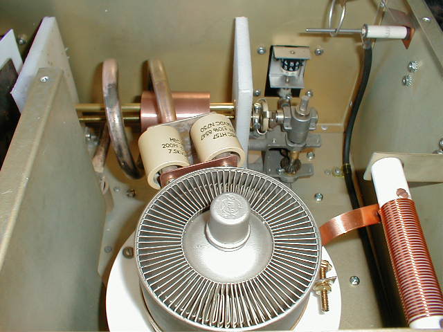
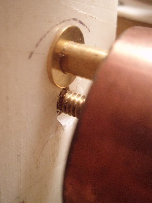
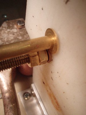
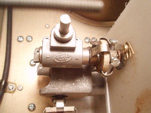
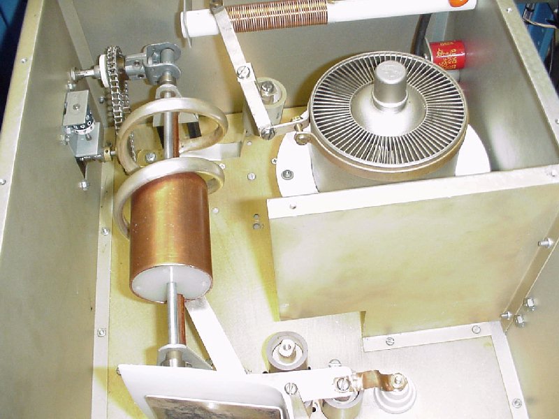
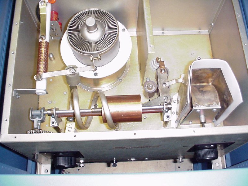
The B+ is delivered to the tube via the copper strap, that simply is held underneath the anode clamp. The RF choke was the one that came with the 14 MHz RF deck, except that only the wide spaced turns are used - the rest of the choke was cut off so the choke was shortened, and the end support bracket was moved several inches toward the rear of the RF deck (as you can see in the photo, in which the two original mounting screws for the RF choke support bracket are still plainly visible). The final RF choke was 42 turns of #18 enamel wire on a .7" diameter Teflon form, 2.75" long. A pair of right angle drives turn a 1/4-20 threaded brass rod, that moves the copper shorting slug into the coil for tuning. Unit is shown tuned to 50.150 MHz. The 1.75" OD copper tuning slug has Teflon plugs in each end, fastened with a brass screw running through the slug. A 9/32" O.D. piece of brass hobby tubing (held in place by 1/4" O.D. brass rod running through it) supports the slug by running through the top of it. The slug is moved back and forth by turning a threaded brass rod that goes through the center of the slug. The threaded brass rod goes through a panel bearing with a 1/4-20 brass nut silver soldered to it, which is mounted on a bracket silver soldered to the inside center of the 1.75" long slug. The threaded brass rod and the 1/4" brass support rod are insulated from ground, and supported by the two HDPE end plates.
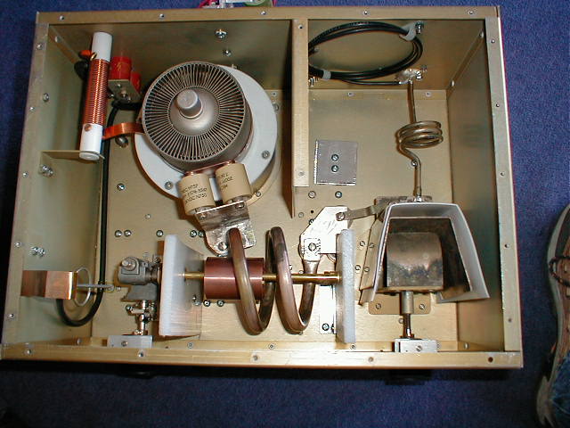
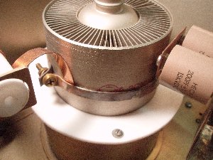
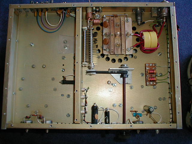
Overall view of the RF deck from the top. The coil was made by using almost two of the turns of the standard 14 MHz coil that came with the 3000D (1/2" diameter tubing, 3.25" ID, 3" long). The L coil was similarly made by using 3 turns from the original L coil (3/16"diameter tubing, 1.5"ID). The original tuning shaft was left in its same location after removing the flapper tuning mechanism that came in the 14 MHz unit. The original loading capacitor was used without any changes, except that the fixed doorknob capacitors in parallel with the variable capacitor (located under the silver plated brass plate at the right end of the coil) were changed from 4 capacitors to 3 capacitors (two 33 pF and one 25 pF). Instead of an RF choke on the output connector, I used a shorted quarter wavelength of Teflon coax to provide additional second harmonic attenuation. The initial test setup for checking out the tank circuit was to temporarily place an 1800 ohm carbon resistor between the tube's plate and chassis ground, and then connect an MFJ-259 Antenna Analyzer to the output connector.
In the original RF deck, there were two ceramic standoffs that pushed down from the perforated cover onto the cooling fins of the tube to hold it in place. I replaced these with a single teflon spacer between the cover and the center of the anode, so there would not be any obstruction air passing through the cooling fins.
 |
 |
|
 |
 |
 |
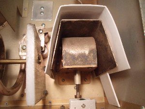
The variable inductor is probably the most usual part of the RF Deck modification. Hopefully, these notes will help anyone who is interested to understand what I did, so they can more easily get started on their own construction. Two 1/2" thick HDPE 4" wide by 6" high end plates were used to support the slug assembly as it moves into the coil to reduce the inductance and tune the tank circuit. The end plates were spaced 6" apart and secured to the chassis with angle aluminum brackets or the right angle drive assembly; they were mounted 3/4" out away from the front insdie panel of the RF Deck. The HDPE end plate next to the loading capacitor is actually only 3" wide on the bottom - it has a 1" x 3" notch cut out of it to provide clearance for the connector plate and fixed doorknob capacitors between the loading capacitor and the tank coil.
 |
 |
 |
 |
 |
 |
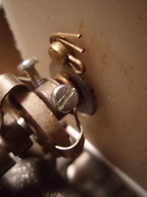
The slug shafts were located so the 1-3/4" long slug (which is 1-3/4" in diamater) runs through the centerline of the tank coil, which is 3-1/2" above the bottom of the plate compartment. The threaded rod goes through the center of the slug, and the brass hobby tubing for support and alignment runs through the slug 1/2" above it. The threaded rod goes through bushings on each HDPE end plate, and is kept from moving back and forth by the flexible coupling connection it to the right angle drive assembly and by the locked double nuts on the far end of the shaft. The alignment tubing is held betwee the two HDPE end plates by 1/4" brass washers that go over the 1/4" brass rod that runs through the alignment tubing and is secured on the outside of the HDPE end plates by cotter pins. If you have more clearance, you could also use 1/4" brass threaded rod with nuts on each end to secure the alignment tubing. An extra piece of teflon sheet was inserted between the variable loading capacitor plate and the HDPE end piece to prevent arcing off the ends of the brass rod which extends through the end piece to secure it.
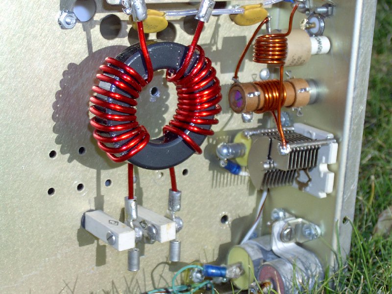
The
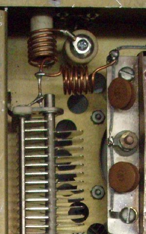
T match input arrangement is shown above. The input
tuning capacitor is a half-meshed 100 pF unit. Both L1
and L2 coils are 6 turns of #14 wire, 1/2" I.D, approximately
.75" long. The coupling capacitor from the
input connector is 1000 pF and the input coil L1 is wound on a
ceramic coil form with a brass slug. A small piece of 1/4" diameter
brass rod was silver soldered to the threaded adjustment shaft
of the adjustable ceramic coil form used for L1, to make the
brass slug.
The filament choke is #10 wire (5 bifilar wound turns) through a pair of toroids I happened to have in the junkbox (with a calculated voltage drop at 51 amps of about 0.2 VAC). Input tuning is "set and forget" but I rigged up a small belt drive system so I could tweak the input tuning capacitor when the amp was in operation.
The initial test setup for checking the input circuit was to temporarily place a 50 0hm carbon resistor between the little standoff where L2 is supported and chassis ground and then connect an MFJ-259 Antenna Analyzer to the input connector. Both L1 and L2 were squeezed and spread and L1 slug adjusted until the input impedance (with an aluminum lid placed over the compartment) showed a purely resistive 50 match, centered on 50.150.
The amp easily delivers 1500w output with under 100w drive. The advantages of this amp are:
1. You never have to worry about over driving it.
2. It is instant on, with no warm-up time.
3. It has plenty of capacity for full duty cycle such as the digital modes.
4. With a soft start on the filament, it should run forever at amateur power levels (actually this may not even be necessary, since the filament transformer probably already limits the inrush current to the cold filament).
5. It produces a very clean signal with no harmonics.
Some
of the other modifications which were performed to the entire
unit include:
1. The over-current sensing circuit inside the amp was disabled.
2. The rectifier diodes were replaced with 8 diode blocks from K2AW (full wave bridge configuration with rectifier blocks in parallel and equalization resistors).
3. The driver power supply and driver were removed.
4. Because the plate supply was changed to a capacitor input filter, the preferred design for a transformer was one which will provide 3300 VAC. The existing transformer was replaced with a much larger transformer, which provides 3080 VAC. A "buck/boost" transformer was added to increase the primary voltage to provide 5 kv DC B+ key down.
5. The time delay relay to short out the heating element in one side of the primary of the B+ transformer was changed from .5 second to 4 seconds; this time delay seems to be just about right for the amount of capacitance used in the filter.
6. The B+ filter choke was removed, and 24 uF from 22 electrolytic capacitors in series (560 uF , 400 VDC each) was added in parallel with a pair of 32 uF, 4500 VDC oil filled filter capacitors wired in series for a total of 40 uF. The electrolytic capacitors were sandwiched between two pieces of 1/8" thick high density polyethylene sheet.
7. The four 20,000 ohm bleeder resistors were replaced with (22) five watt 51 k resistors (one across each electrolytic).
8. A 100 ohm 200 watt resistor was added in series with one of the legs of the filament primary transformer, which causes the tube filament to warm up at half voltage (around 3 vac). This resistor is shorted out after approximately 5 seconds with a zero-crossing solid state relay. However, this may be overkill, since the shorted filament transformer very probably does not provide enough inrush current to the cold filament to cause damage.
9. A relay box was added inside the amp to control external antenna relays, as well as to short out the 50 K cutoff resistor and put the amp into XMIT mode when a high impedance short to ground is provided from the station sequencer. The relay box includes a 28 VDC power supply (to run the external coaxial relays) as well as a 12 VDC supply (to power the relays in the box). As can be seen from the photo below, a switch was added on the front panel, to select whether power was applied to the relay box when (1) the 3CX3000 amp is plugged into the wall but not necessarily running or switched in, (2) switched in and operating with the B+ applied, or (3) the power to the relay box can simply be turned off. Since the 28 VDC is used to power external coaxial antenna relays on receive, it is usually left powered on whenever power is switched on to the ham shack.
10. A small variac was added to one leg of the filament primary transformer so that the filament voltage could be adjusted accurately.
11. A larger blower was installed on the bottom of the RF deck. I used an old blower (4" wide x 10" diameter) from a Jennair stovetop, and mounted a 240 VAC 1/10 horsepower electric motor to it. In addition, I added a high volume "sucking fan" on top of the RF deck (to reduce back pressure on the blower as well as draw cool air down into the the tank compartment across the components there.
12. An outboard RF Bias Switching box was added to the input of the amp (the one I previously used on my 2m 8877 amp). With the RF bias switching, there is virtually no idling current during transmit mode, and the tube is placed back into cutoff whenever there is no drive. This keeps the tube running cooler on modes with less than 100% duty cycle.
13. The original 1.5 ohm 20w wirewound "glitch resistor" between the B+ supply and the tube anode was replaced with a 100 ohm, 100w wirewound, and mounted on the plate transformer, directly in front of the cabinet cooling fans.
The following additional photos illustrate how the amplifier was configured:

QRO 50 MHZ LOW PASS FILTER
Revised 8 August, 2019
1. The over-current sensing circuit inside the amp was disabled.
2. The rectifier diodes were replaced with 8 diode blocks from K2AW (full wave bridge configuration with rectifier blocks in parallel and equalization resistors).
3. The driver power supply and driver were removed.
4. Because the plate supply was changed to a capacitor input filter, the preferred design for a transformer was one which will provide 3300 VAC. The existing transformer was replaced with a much larger transformer, which provides 3080 VAC. A "buck/boost" transformer was added to increase the primary voltage to provide 5 kv DC B+ key down.
5. The time delay relay to short out the heating element in one side of the primary of the B+ transformer was changed from .5 second to 4 seconds; this time delay seems to be just about right for the amount of capacitance used in the filter.
6. The B+ filter choke was removed, and 24 uF from 22 electrolytic capacitors in series (560 uF , 400 VDC each) was added in parallel with a pair of 32 uF, 4500 VDC oil filled filter capacitors wired in series for a total of 40 uF. The electrolytic capacitors were sandwiched between two pieces of 1/8" thick high density polyethylene sheet.
7. The four 20,000 ohm bleeder resistors were replaced with (22) five watt 51 k resistors (one across each electrolytic).
8. A 100 ohm 200 watt resistor was added in series with one of the legs of the filament primary transformer, which causes the tube filament to warm up at half voltage (around 3 vac). This resistor is shorted out after approximately 5 seconds with a zero-crossing solid state relay. However, this may be overkill, since the shorted filament transformer very probably does not provide enough inrush current to the cold filament to cause damage.
9. A relay box was added inside the amp to control external antenna relays, as well as to short out the 50 K cutoff resistor and put the amp into XMIT mode when a high impedance short to ground is provided from the station sequencer. The relay box includes a 28 VDC power supply (to run the external coaxial relays) as well as a 12 VDC supply (to power the relays in the box). As can be seen from the photo below, a switch was added on the front panel, to select whether power was applied to the relay box when (1) the 3CX3000 amp is plugged into the wall but not necessarily running or switched in, (2) switched in and operating with the B+ applied, or (3) the power to the relay box can simply be turned off. Since the 28 VDC is used to power external coaxial antenna relays on receive, it is usually left powered on whenever power is switched on to the ham shack.
10. A small variac was added to one leg of the filament primary transformer so that the filament voltage could be adjusted accurately.
11. A larger blower was installed on the bottom of the RF deck. I used an old blower (4" wide x 10" diameter) from a Jennair stovetop, and mounted a 240 VAC 1/10 horsepower electric motor to it. In addition, I added a high volume "sucking fan" on top of the RF deck (to reduce back pressure on the blower as well as draw cool air down into the the tank compartment across the components there.
12. An outboard RF Bias Switching box was added to the input of the amp (the one I previously used on my 2m 8877 amp). With the RF bias switching, there is virtually no idling current during transmit mode, and the tube is placed back into cutoff whenever there is no drive. This keeps the tube running cooler on modes with less than 100% duty cycle.
13. The original 1.5 ohm 20w wirewound "glitch resistor" between the B+ supply and the tube anode was replaced with a 100 ohm, 100w wirewound, and mounted on the plate transformer, directly in front of the cabinet cooling fans.
The following additional photos illustrate how the amplifier was configured:
FRONT VIEWS 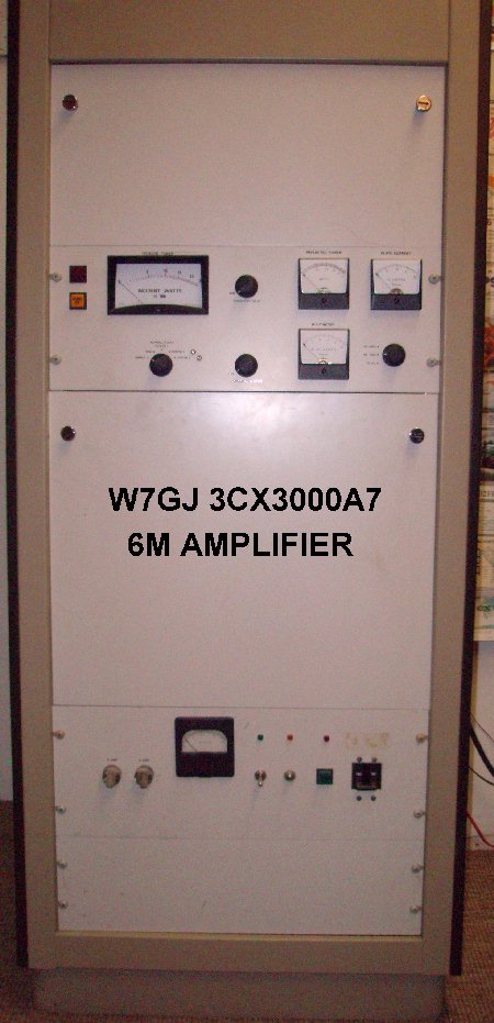      |
REAR VIEWS  Note - the original single 16 uF, 7500 VDC oil filter capacitor pictured above was later replaced with a pair of 32 uF, 4500 VDC oil filled filter capacitors in series. The new 100 ohm, 100w "glitch resistor" in the B+ line was mounted on top of the plate transformer.       |
QRO 50 MHZ LOW PASS FILTER
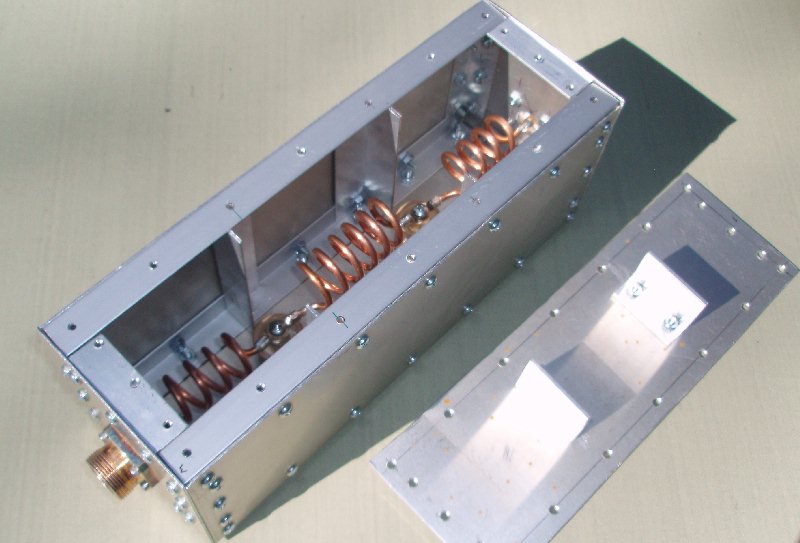
| This very heavy duty 50
MHz Low Pass Filter was constructed by using a pair
of 50 pF, 15 kVDC ceramic doorknob capacitors, and
three air wound self supporting coils. The center coil ( L2 ) is 6 turns, 2.5" long, using #6 AWG copper wire wound on a 7/8" diamter form. Input and Output coils ( L1 and L3 ) are each 4 turns, 2'' long, using #6 AWG copper wire wound on a 3/4" diameter form. The enclosure was built to fit the space required for the coils. The box is 12" long, 4" wide and 4.5" high. Baffles were mounted around each capacitor to prevent enclosure resonance at UHF harmonics. Insertion loss was measured at less than .06 dB, with attenuation greater than 24 dB at 100 MHz. |
 |
||
ADDITIONAL PHOTOS OF HOW OTHERS
HAVE DONE THE
6M MODIFICATION TO 14 MHZ & 27 MHZ UNITS
6M MODIFICATION TO 14 MHZ & 27 MHZ UNITS
 |
 |
 |
 |
Revised 8 August, 2019